
Monolithic modular high-frequency plasma source

Pending Publication Date: 2021-04-01
APPLIED MATERIALS INC
View PDF3 Cites 1 Cited by
  • Summary
  • Abstract
  • Description
  • Claims
  • Application Information

AI Technical Summary

Benefits of technology

The patent text describes a source array that includes a monolithic plate with protrusions that extend from its surface. This source array is designed to be used in a processing tool. The monolithic structure provides a more efficient and reliable source of ions for the tool. The processing tool also includes a housing with conductive openings that surround each protrusion to improve the efficiency of the tool. Overall, this patent presents a way to create a more effective and reliable ion source for processing tools.

Problems solved by technology

This has the potential of generating plasma non-uniformities within the processing chamber.
Furthermore, exposing the applicator to the plasma environment may lead to a more rapid degradation of the applicator.
Such configurations have reduced coupling with the interior of the chamber and, therefore, does not provide an optimum plasma generation.
Additionally, variations of the interface (e.g., positioning of the applicator, surface roughness of the applicator and / or the dielectric plate, angle of the applicator relative to the dielectric plate, etc.) at each applicator and across different processing tools may result in plasma non-uniformities.
For example, with discrete components, small variations (e.g., variations in assembly, machining tolerances, etc.) can result in plasma non-uniformities that negatively affect processing conditions within the chamber.

Method used


Image

  • Monolithic modular high-frequency plasma source
  • Monolithic modular high-frequency plasma source
  • Monolithic modular high-frequency plasma source

Examples


Embodiment Construction

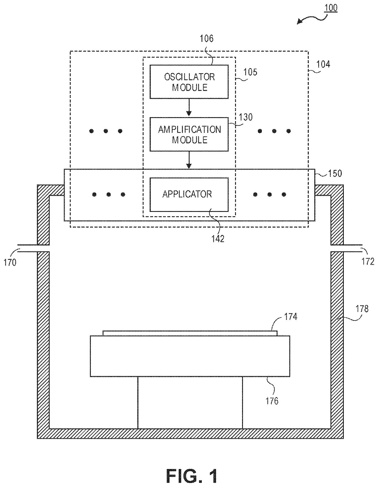
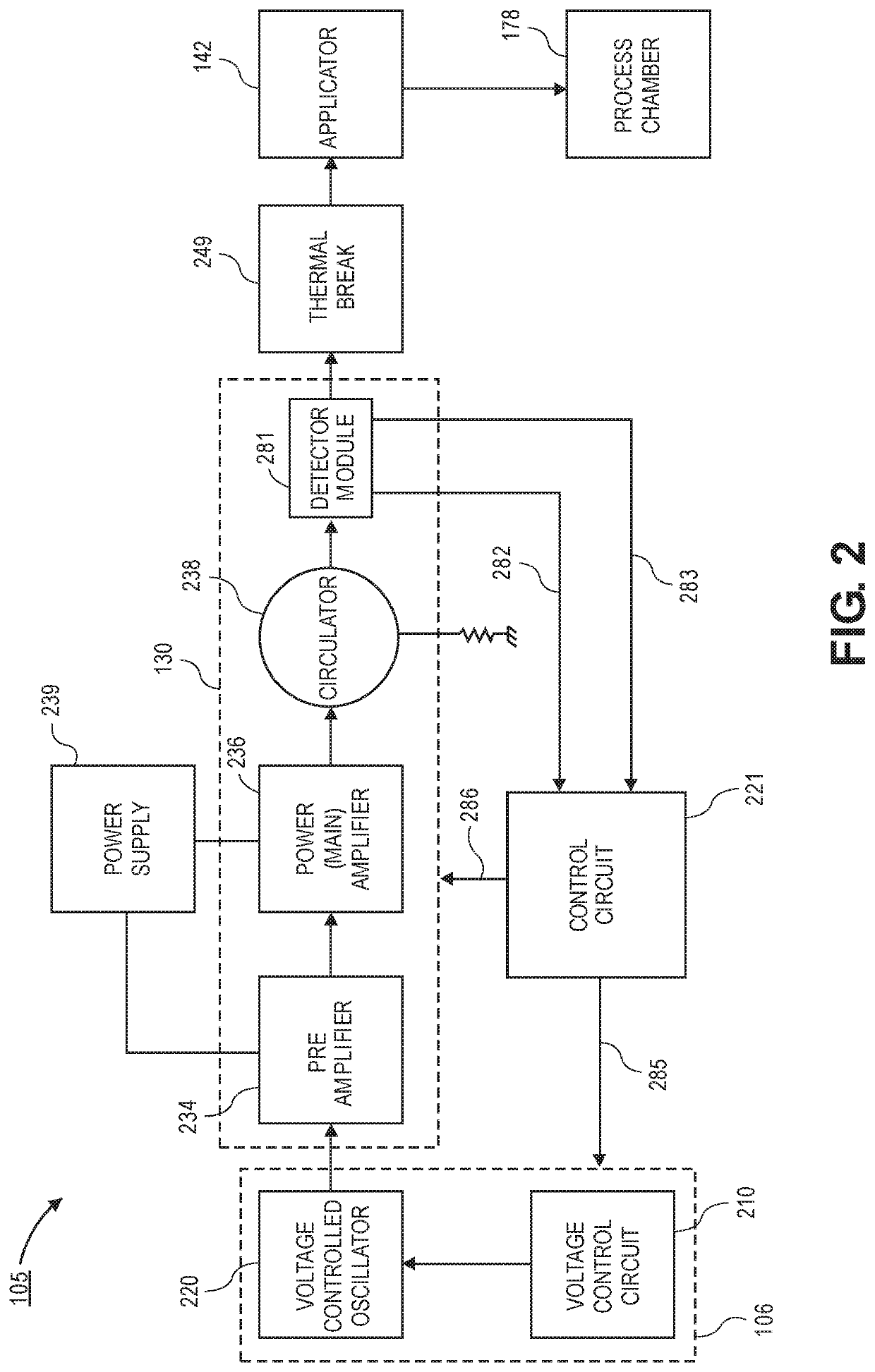
[0020]Systems described herein include monolithic source arrays for high-frequency plasma sources. In the following description, numerous specific details are set forth in order to provide a thorough understanding of embodiments. It will be apparent to one skilled in the art that embodiments may be practiced without these specific details. In other instances, well-known aspects are not described in detail in order to not unnecessarily obscure embodiments. Furthermore, it is to be understood that the various embodiments shown in the accompanying drawings are illustrative representations and are not necessarily drawn to scale.

[0021]As noted above, high-frequency plasma sources with discrete applicators may result in plasma non-uniformities within a chamber and in non-optimum injection of the high-frequency electromagnetic radiation into the chamber. The non-uniformities in the plasma may arise for different reasons, such as assembly issues, manufacturing tolerances, degradation, and t...


PUM


Abstract

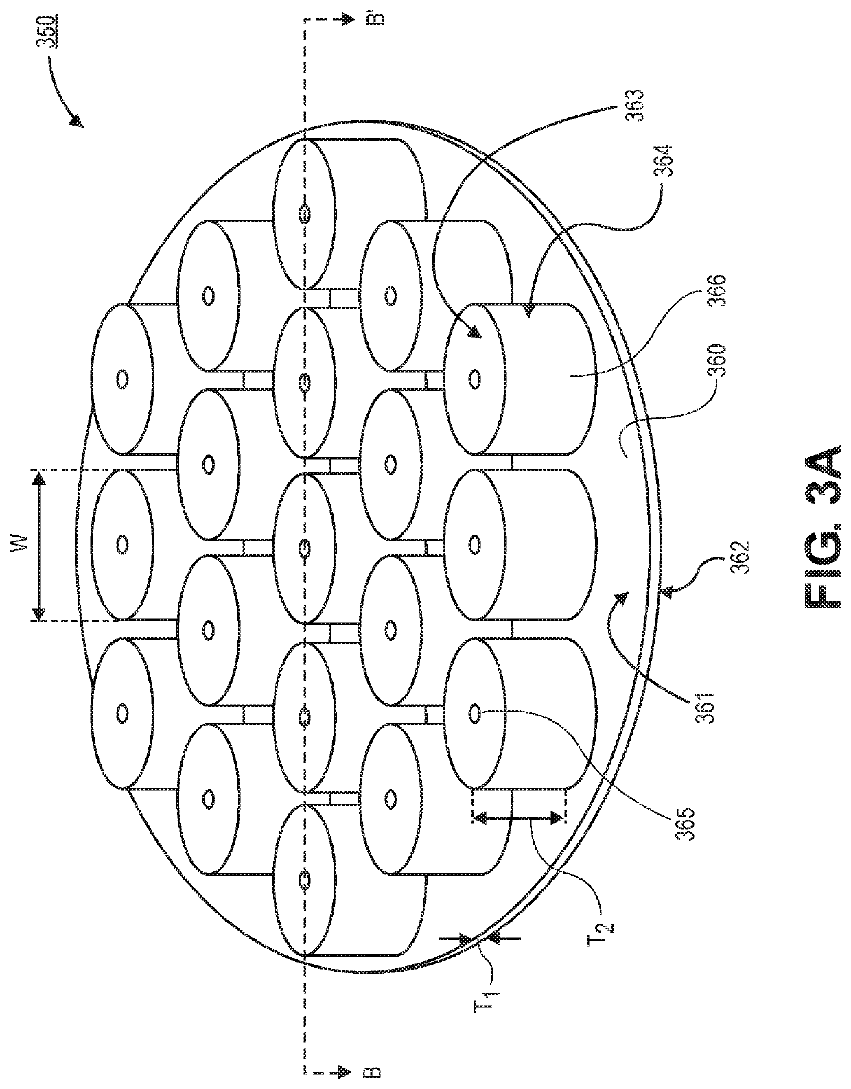
Embodiments disclosed herein include a monolithic source array. In an embodiment, the monolithic source array comprises a dielectric plate having a first surface and a second surface opposite from the first surface. The monolithic source array may further comprise a plurality of protrusions that extend out from the first surface of the dielectric plate, wherein the plurality of protrusions and the dielectric plate are a monolithic structure.

Description

BACKGROUND1) Field[0001]Embodiments relate to the field of semiconductor manufacturing and, in particular, to monolithic source arrays for high-frequency plasma sources.2) Description of Related Art[0002]Some high-frequency plasma sources include applicators that pass through an opening in a dielectric plate. The opening through the dielectric plate allows for the applicator (e.g., a dielectric cavity resonator) to be exposed to the plasma environment. However, it has been shown that plasma is also generated in the opening in the dielectric plate in the space surrounding the applicator. This has the potential of generating plasma non-uniformities within the processing chamber. Furthermore, exposing the applicator to the plasma environment may lead to a more rapid degradation of the applicator.[0003]In some embodiments, the applicators are positioned over the dielectric plate or within a cavity into (but not through) the dielectric plate. Such configurations have reduced coupling wit...

Claims


Application Information

Patent Timeline
IPC IPC(8): H01J37/32
CPCH01J37/3211H01J2237/3321H01J2237/332H01J37/32431H01J37/32238H01J37/32119
Inventor CHUA, THAI CHENGKRAUS, PHILIP ALLAN
Owner APPLIED MATERIALS INC
Learn More