Multi-spot ophthalmic laser

a laser and multi-spot technology, applied in the field of laser devices, can solve the problems of thermal shock waves that are detrimental to the regeneration process, too much laser energy, etc., and achieve the effect of high energy intensity spots

Pending Publication Date: 2021-05-06
ELLEX MEDICAL
View PDF0 Cites 1 Cited by
  • Summary
  • Abstract
  • Description
  • Claims
  • Application Information

AI Technical Summary

Benefits of technology

[0012]Alternatively, the optical beam profiling module comprises a diffractive optical element and lens in the optical path of the laser output that modifies the beam optically to produce high energy intensity spots.
[0013]In a further alternative the optical beam profiling module comprises a mask that blocks parts of the output beam profile only allowing transmission of selected areas of the laser beam and a focusing lens that images the output of the laser module after the mask to form high intensity spots.
[0014]In a still further alternative the optical beam profiling module comprises a micro-lens array and focusing lens that images the output of the laser module to form high intensity spots.

Problems solved by technology

However, in order to be effective the RPE cells need to be targeted with an appropriate energy while neighbouring cells are not exposed to laser energy, or at least are exposed to laser energy at such a low level that there is no discernible effect.
Similarly, too much laser energy produces a thermal shock wave that is detrimental to the regeneration process.

Method used


Image

  • Multi-spot ophthalmic laser
  • Multi-spot ophthalmic laser
  • Multi-spot ophthalmic laser

Examples


first embodiment

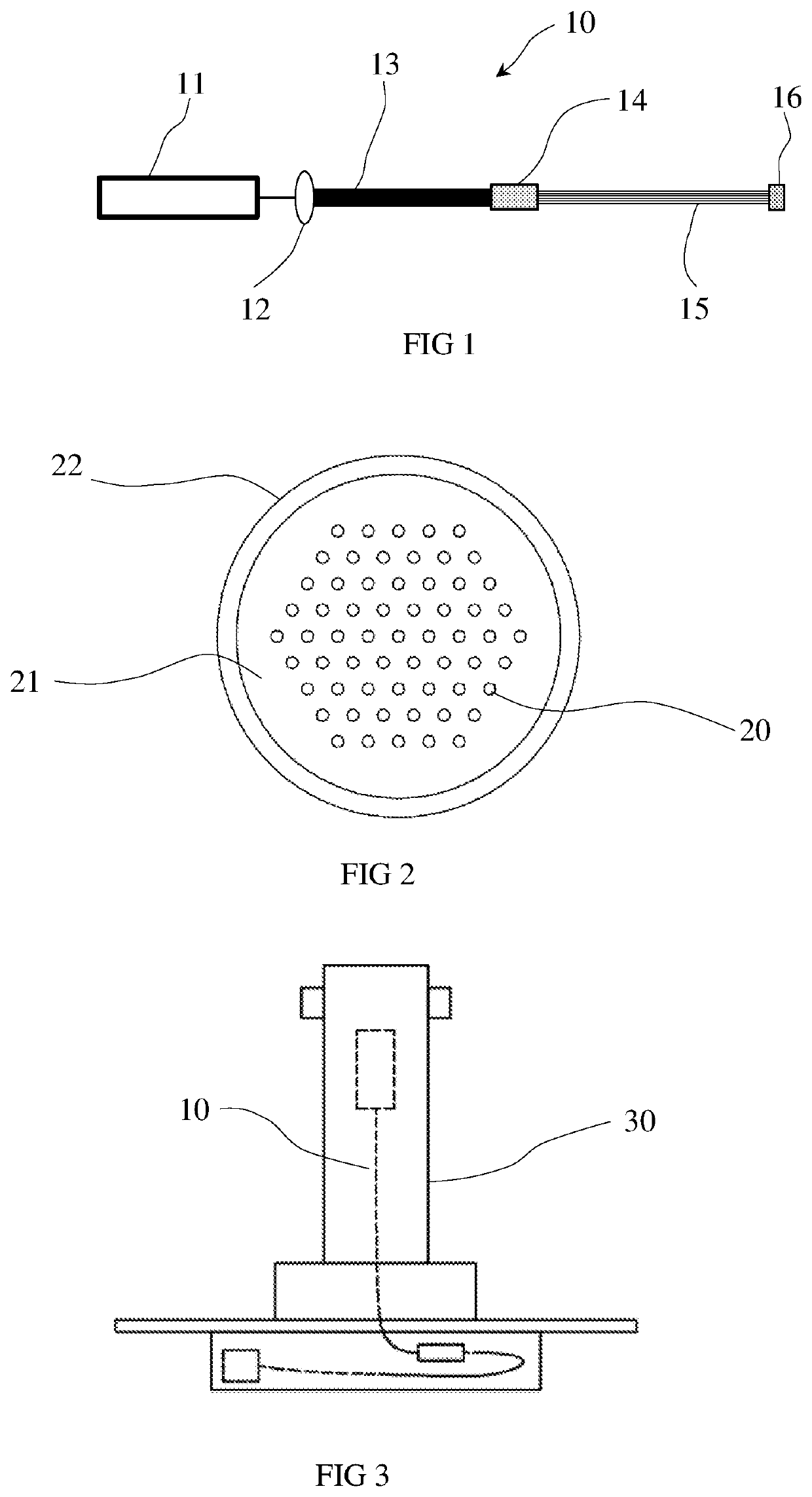
[0032]Referring to FIG. 1 there is a shown the invention comprising a multi-spot ophthalmic laser device 10 consisting of a laser module 11, optics 12, multimode fibre 13, coupler 14, multi-fibre bundle 15 and output head 16.

[0033]The laser module may be any suitable laser that generates the appropriate output. The preferred embodiment of the laser module 11 is frequency doubled, Q-switched flashlamp-pumped Nd:YAG laser producing 532 nm laser pulses. The laser cavity is suitably of conventional design having a 100% reflecting end mirror and a partial reflecting output coupler. The laser rod is excited by a flashlamp that is energized by a high voltage power supply. A passive Q-switch allows the cavity energy to be delivered as very short, high energy pulses. An alternate source of excitation is a semiconductor laser that is used to pump the laser rod.

[0034]Although a flashlamp pumped Nd:YAG laser is the preferred embodiment for the laser cavity the invention is not limited to this p...

second embodiment

[0045]the invention is shown in FIG. 10. In this embodiment the optical beam profiling module 100 utilizes a diffractive optical element 101 that modifies the output 11a of the laser module 11 optically to produce multiple spatially distributed laser spots. Looking at FIG. 10 in detail, the laser module output 11a is modified by the diffractive optical element 101 and then focused by a focusing lens 102 to a target 103. The energy peaks at the target 103 have the profile displayed in the enlargement 103a of the target 103 and the graph 104. The diffractive optical element 101 is selected to achieve the energy intensity profile of graph 104 with a spot diameter to space ratio in the range 1:2 to 1:20.

[0046]Three diffractive optical elements 101 have been built to understand the optimal spacing and the optimal spot for the element. The ideal configuration should ensure all neighbouring RPE cells around an individual treated cell remain intact and free of energy absorption. These diffr...

third embodiment

[0047]the invention is shown in FIG. 11. In this embodiment the optical beam profiling module 110 has a masked coating 111 that blocks the undesired parts of the beam 11a and transmits the desired parts of the laser beam 11a. The optical beam profiling module 110 also includes a beam expander / homogenizer 111a that modifies the profile of the beam 11a to have a top hat profile before the mask 111. Looking at FIG. 11 in detail, the laser module output 11a is selectively blocked by the mask 111 and then focused by focusing lens 112 to a target 113. The energy peaks at the target 113 have the profile displayed in the enlargement 113a of the target 113 and the graph 114. The masked coating 111 can partially absorb or reflect the incident light to achieve the energy intensity profile of graph 114 with a spot diameter to space ratio in the range 1:2 to 1:20. In a variation on this embodiment the mask could be applied directly to the focusing lens.


PUM

PropertyMeasurementUnit
wavelength in theaaaaaaaaaa
diameteraaaaaaaaaa
core diameteraaaaaaaaaa

Abstract

A multi-spot ophthalmic laser device that produces spatially distributed laser spots with the spatial distribution of the laser spots defined by a spot diameter to space ratio in the range 1:2 to 1:20. The multi-spot ophthalmic laser device comprises: a laser module producing a laser pulse or sequence of laser pulses each having: a pulse duration in the range of 10 ps to 20 μs; a wavelength in the range 500 nm to 900 nm; and a pulse energy in the range 10 μJ to 10 mJ per pulse; and an optical beam profiling module that modifies an output beam profile of each pulse of the laser module to deliver multiple spatially distributed laser spots of defined size and energy. The multi-spot ophthalmic laser device is used in a method of improving the function of the retina of a human eye by irradiation through the cornea of the eye to the retinal pigmented epithelium by a treatment laser having a beam profile with spatially distributed energy peaks.

Description

FIELD OF THE INVENTION[0001]The present invention relates to the field of laser devices and in particular to an ophthalmic laser device for treatment of eye problems. More particularly, the invention relates to a multi-spot ophthalmic laser.BACKGROUND TO THE INVENTION[0002]Lasers have been used for many years to treat retinal disorders, predominately using their ability to coagulate tissue. The degree of laser energy absorption in retinal layers and structures is highly dependent on the wavelength used and the effectiveness of controlling the focal point and the energy profile of the laser beam.[0003]In our earlier filed Australian patent application number 2008255642 we describe an ophthalmic laser device useful for improving the function of the retina of the human eye. In the background section of the application we explain the need for effective retinal treatments and describe a laser treatment device that produces a uniform treatment effect. The content of AU2008255642 is incorp...

Claims


Application Information

Patent Timeline
Patent Type & Authority Applications(United States)
IPC IPC(8): A61F9/008G02B6/04G02B27/09G02B19/00
CPCA61F9/008G02B6/04G02B27/0944A61F2009/00872G02B19/0047A61F2009/00863G02B19/0009A61F9/00823A61F9/00814A61F9/00817A61B2018/00589A61B2018/00779A61B2018/2211A61B2018/2294A61B2018/2266A61F9/00821A61B18/20A61B18/203A61B2018/00321
Inventor XIA, WEIPREVIN, VICTORMCWILLIAMS, ROBINMARSHALL, JOHN
Owner ELLEX MEDICAL
Why Eureka
Try Eureka