Fireproof and thermal insulator product

a technology of thermal insulation and product, which is applied in the field of fireproof and thermal insulation products, can solve the problems of high cost and heavyness of thermal insulation blankets, many aircraft parts are at risk, and provide thermal insulation, and achieve good thermal insulation capability

Pending Publication Date: 2021-05-20
AIRBUS OPERATIONS SL
View PDF3 Cites 1 Cited by
  • Summary
  • Abstract
  • Description
  • Claims
  • Application Information

AI Technical Summary

Benefits of technology

[0009]A fireproof and thermal insulation laminate has been invented and is disclosed herein that may be embodied to provide a product that is fireproof and has also good thermal insulation capability, to avoid having aircraft structures surrounding fire source reaching high temperatures that could damage the structure.
[0012]The fireproof and thermal insulation laminate may be embodied to provide one or more of the following advantages: low cost; light weight; good fire-proof and thermal insulation capabilities; environmentally friendly; and able to be integrated with structural panels, ducts, casing and other structures such as in an aircraft. Moreover the fireproof and thermal insulation laminate may be embodied to have more rigidity than conventional thermal blankets and thus are less susceptible to collapsing during the manufacturing and / or assembly process. Further, the fireproof and thermal insulation laminate provides good thermal insulation and thus may be used to allow the use in fire-zone designated areas of an aircraft of structural materials having limited high-temperature strength capability.

Problems solved by technology

Many parts of the aircraft are at risk during a fire event.
Thermal blanket insulations are effective suppression of flame penetration and provide thermal insulation, but are expensive and heavy.
Thermal blanket insulations lack of rigidity and thus can collapse during the manufacturing or assembly process.
If the blankets remain collapsed in the aircraft, the blankets loss much of their ability to suppress flame penetration and provide thermal insulation to the regions of the aircraft intended to be covered by a properly deployed blanket.
This option is relevant in many applications due to its performance, however structures submitted to vibrations cannot implement this solution due to the loss of protection under the operation conditions.

Method used


Image

  • Fireproof and thermal insulator product
  • Fireproof and thermal insulator product
  • Fireproof and thermal insulator product

Examples


Embodiment Construction

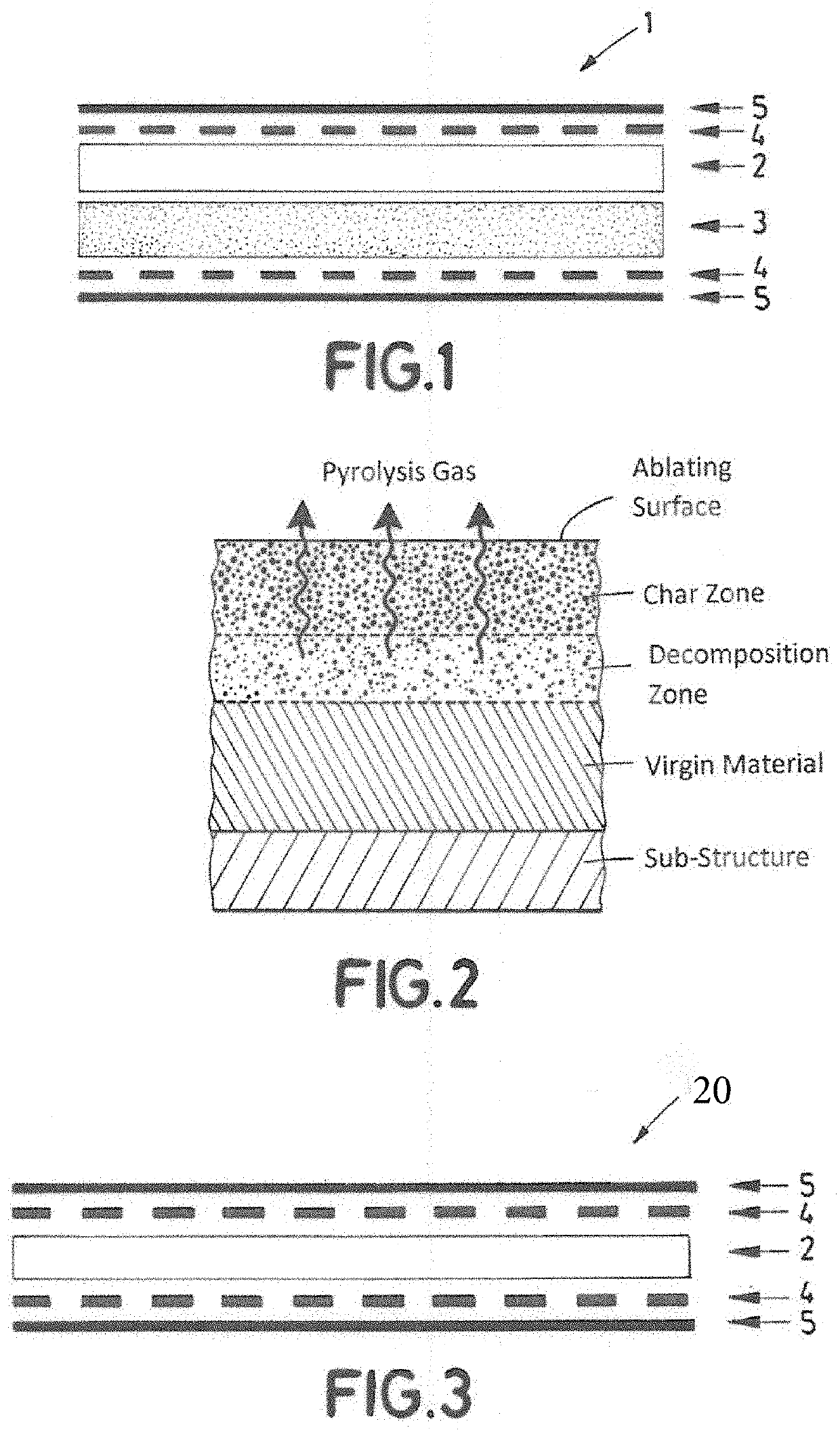
[0025]The term “fireproof” is defined by aeronautical regulations such as: FAR / JAR 25.1191: Firewalls-Definition, AND FAR / JAR 25.865: Fire Protection Of Flight Controls, Engine Mounts And Other Flight Structures.

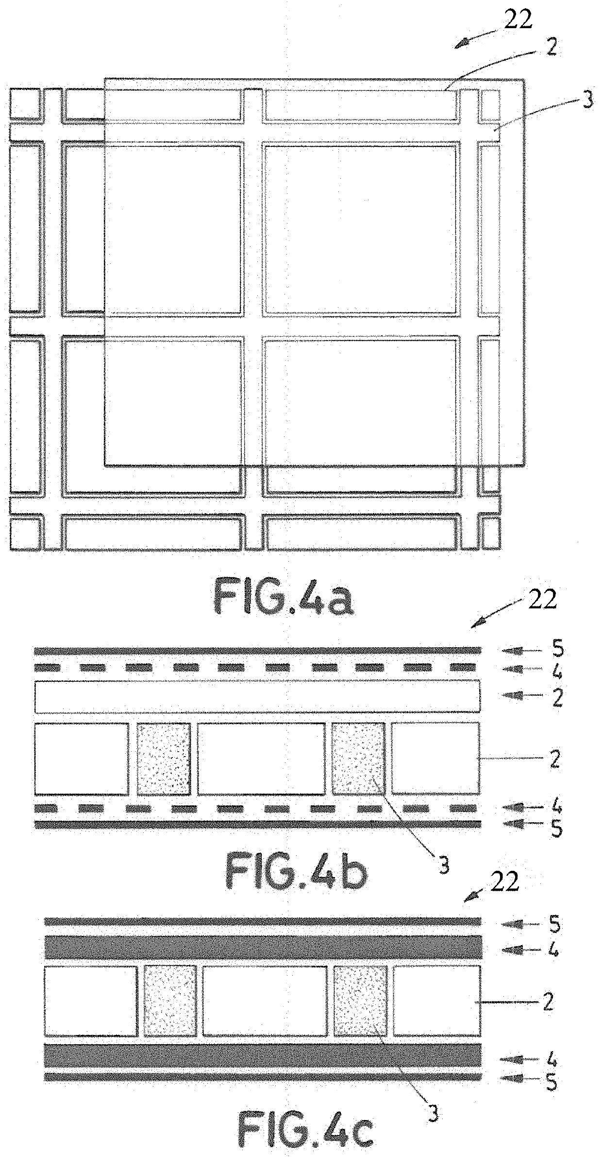
[0026]FIG. 1 shows a first configuration of the fireproof and thermal insulator product 1 of the invention that comprises a stack of layers including a layer of cork 3, and a layer of Earth Silicate material (AES) 2 at the side of the product 1 intended to face the fire. The layer of AES 2 mainly acts as a fireproof barrier, and in a second level as thermal insulator, while layer of cork 3 acts as thermal insulator. The AES layer 2 may be bonded to the cork layer 3 by an adhesive layer or film or by fasteners, such as screws, bolts or clamps.

[0027]The AES and cork layers 2, 3 may be covered by a barrier film(s) 5 that protects the layers 2, 3 from liquids. The barrier films 5 may be a fiber reinforcement plastic (FRP) film 4 that covers an exposed side of the AES layer and a...


PUM

PropertyMeasurementUnit
temperatureaaaaaaaaaa
distanceaaaaaaaaaa

Abstract

A fireproof and thermal insulator product (1) including an Alkaline Earth Silicate (AES) material (2), and at least one of the following: a liquid barrier film (5), an FRP (Fiber Reinforcement Plastic) layer (4), cork (3), wherein the liquid barrier film (5) and the FRP layer (4) are staked onto the AES material (2), and wherein the cork (3) material is also staked onto the AES material (2) or embedded into said AES material (2) in where said cork (3) is configured as a plurality of strips performing a grid structure infilled with the AES material (2).

Description

RELATED APPLICATION[0001]This application claims priority to European Patent Application 19383000-7, filed Nov. 14, 2019, the entirety of which is incorporated by reference.TECHNICAL FIELD[0002]The invention refers structures and associated systems with protection against the consequences of a fire event, particularly flame penetration, and that also provide thermal insulation capability. The invention is particularly applicable in different parts of aircrafts, such as fixed wing airplanes and helicopters.BACKGROUND[0003]Many parts of the aircraft are at risk during a fire event. To ensure normal operation of the aircraft, the structure and associated systems should be protected against the fire event consequences. For these purposes, several materials and solutions have been tested and installed to prevent the consequences of the fire events. Two main effects need to be solved depending on the application: flame penetration and thermal insulation.[0004]The flame penetration issue i...

Claims


Application Information

Patent Timeline
Patent Type & Authority Applications(United States)
IPC IPC(8): B64C1/40B32B7/12B32B7/08B32B9/00B32B9/04B32B27/12B32B27/30B32B27/36B32B27/28B32B9/02H01M2/02
CPCB64C1/40B32B7/12B32B7/08B32B9/005B32B9/045B32B27/12B64C2001/0054B32B27/36B32B27/285B32B9/02B32B9/047H01M2/029H01M2/0262B32B27/304B32B3/12B32B21/08B32B27/06B32B27/302B32B17/062B32B9/042B32B17/10073B32B33/00B32B2262/106B32B2262/067B32B2307/558B32B2307/306B32B2605/18B32B2307/718B32B27/288B32B2262/101B32B2260/021B32B2260/046B32B3/06B32B3/10B32B2457/10B32B2597/00B32B2307/3065B32B2307/304B32B5/02Y02E60/10H01M50/116B32B2307/7265H01M2220/20
Inventor KEMPF, MANUELBUTRAGUENO-MARTINEZ, ASUNCIONBALLESTERO MÉNDEZ, JORGEINIESTA LOZANO, FERNANDOHERNAIZ LOPEZ, GUILLERMOVAZQUEZ SANCHEZ, PABLOARANA HIDALGO, ALBERTOVAZQUEZ CASTRO, JESUS JAVIER
Owner AIRBUS OPERATIONS SL
Why Eureka
Try Eureka