
Detector for optically detecting at least one object

Inactive Publication Date: 2021-07-22
TRINAMIX GMBH
View PDF0 Cites 4 Cited by
  • Summary
  • Abstract
  • Description
  • Claims
  • Application Information

AI Technical Summary

Benefits of technology

The present invention proposes an optical detector that can acquire desired longitudinal information about an object without requiring a modulation frequency to be applied. The detector also has a high degree of simplicity, making it suitable for various applications such as machine control and gaming. The technical effects of the invention include simplifying the optical setup of the detector, reducing the cost of the detector, and improving the efficiency of the detector.

Problems solved by technology

Despite the advantages implied by the above-mentioned devices and detectors, several technical challenges remain.
Thus, transparent detectors or an expensive beam splitter are necessary.
This results in drawbacks concerning achievable quantum efficiency, signal-to-noise-ratio and optical resolution.
This discussion of known concepts, such as the concepts of several of the above-mentioned prior art documents, clearly shows that some technical challenges remain.

Method used


Image

  • Detector for optically detecting at least one object
  • Detector for optically detecting at least one object

Examples


Embodiment Construction

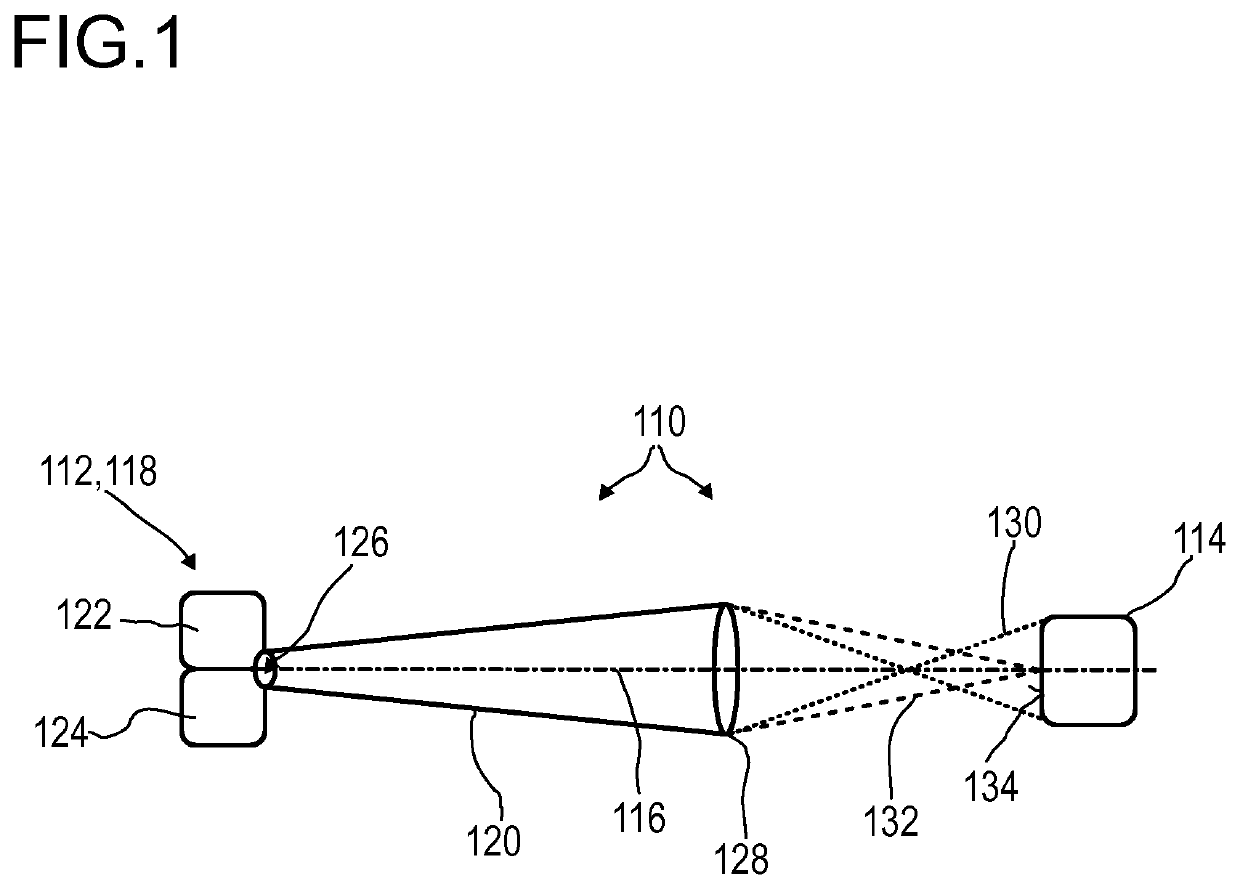
[0225]FIG. 1 illustrates, in a highly schematic fashion, an exemplary embodiment of an optical detector 110 according to the present invention, for determining a position of at least one object 112. However, other embodiments are feasible. The optical detector 110 comprises at least one longitudinal optical sensor 114, which, in this particular embodiment, is arranged along an optical axis 116 of the detector 110. Specifically, the optical axis 116 may be an axis of symmetry and / or rotation of the setup of the optical sensor 114. The detector 110 may comprise at least one illumination source 118 adapted to emit at least one light beam 120. The light beam 120 may comprise at least two different wavelengths, wherein the light beam may comprise at least one first portion and at least one second portion having different wavelengths.

[0226]The illumination source 118 may be connected to the object 112 or even be part of the object 112, such that, by way of example, the electromagnetic rad...


PUM


Abstract

A detector (110) for an optical detection of at least one object (112) is disclosed. The detector (110) comprises: —at least one longitudinal optical sensor (114), wherein the longitudinal optical sensor (114) has at least one sensor region (134), wherein the longitudinal optical sensor (114) is designed to generate at least one longitudinal sensor signal in a manner dependent on an illumination of the sensor region (134) by a light beam, wherein the longitudinal sensor signal, given the same total power of the illumination, is dependent on a beam cross-section of the light beam in the sensor region (134); —at least one transfer device (128), wherein the transfer device (128) exhibits at least two different focal lengths in response to at least one incident light beam, wherein the transfer device (128) is adapted to adjust the beam cross-section of at least one first light beam (130) having a first wavelength and at least one second light beam (132) having a second wavelength different from the first wavelength depending on the wavelength of respective light beams, such that in the sensor region (134), the beam cross-section of the first light beam (130) is different from the beam cross-section of the second light beam (132); and—at least one evaluation device (156), wherein the evaluation device (156) is adapted to differentiate the longitudinal sensor signal of the longitudinal optical sensor (114) into a first longitudinal sensor signal dependent on the illumination of the sensor region (134) by the first light beam and into a second longitudinal sensor signal dependent on the illumination of the sensor region (134) by the second light beam, wherein the evaluation device (156) is designed to generate at least one item of information on a longitudinal position of the object (112) by evaluating the first longitudinal sensor signal and the second longitudinal sensor signal.

Description

FIELD OF THE INVENTION[0001]The invention relates to a detector, a detector system and a method for determining a position of at least one object. The invention further relates to a human-machine interface for exchanging at least one item of information between a user and a machine, an entertainment device, a tracking system, a camera, a scanning system and various uses of the detector device. The devices, systems, methods and uses according to the present invention specifically may be employed for example in various areas of daily life, gaming, traffic technology, production technology, security technology, photography such as digital photography or video photography for arts, documentation or technical purposes, medical technology or in the sciences. However, other applications are also possible.PRIOR ART[0002]A large number of optical sensors and photovoltaic devices are known from the prior art. While photovoltaic devices are generally used to convert electromagnetic radiation, ...

Claims


Application Information

Patent Timeline
IPC IPC(8): G01S17/06G01S7/4912
CPCG01S17/06G03B13/20G01C11/02G01S17/46G01S3/786G02B27/1013G01S7/4912G02B27/0172
Inventor VALOUCH, SEBASTIANSEND, ROBERTBRUDER, INGMARANDERMAHR, NIKLASVOGLER, ANDREASASFOUR, JEAN-MICHEL
Owner TRINAMIX GMBH
Learn More