Integrated process for the production of isononanol and gasoline and diesel blending components
a technology of isononanol and gasoline, which is applied in the direction of hydrocarbons from oxygen organic compounds, chemical/physical/physicochemical stationary reactors, catalytic reactions, etc., can solve the problems of inability to integrate processes in a single system in an efficient and cost-effective manner, and the production capacity of isononanol in these oxo processes is limited
- Summary
- Abstract
- Description
- Claims
- Application Information
AI Technical Summary
Benefits of technology
Problems solved by technology
Method used
Image
Examples
example 1
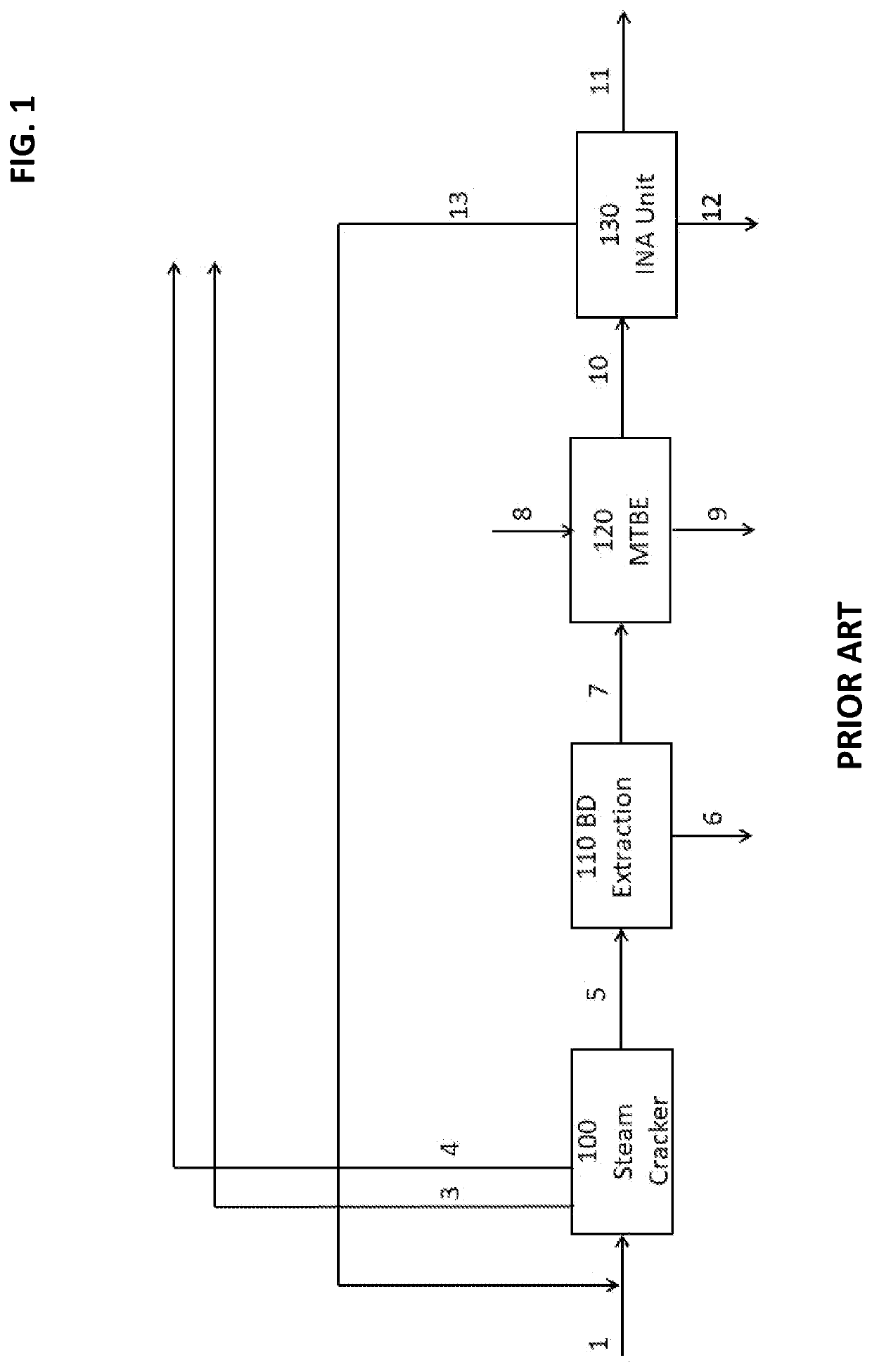
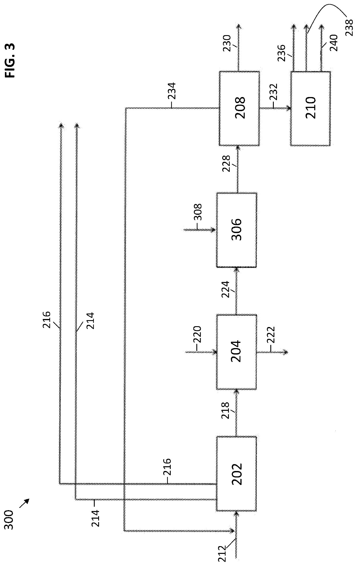
[0071]This example shows the isononanol yield difference between the conventional system shown in FIG. 1 and an embodiment of the present application shown in FIG. 3. In this example, a 500 kilotons per annum (KTA) hydrocarbon feed is used, where the feed mainly consists of C4 hydrocarbons. The components of the hydrocarbon feed are shown in weight % (W %) in the table of FIG. 5A, along with the range of a typical hydrocarbon feed for the present systems. FIG. 5B displays a table showing the differences in yields of various products between the conventional system of FIG. 1 and the embodiment of system 200 of FIG. 3 of the present application. As shown in the table of FIG. 5B, the embodiment of the present application shown in FIG. 3 results in a more than 3-fold increase in isononanol yield as compared with the conventional system of FIG. 1 (588 KTA vs. 158 KTA). This increase in isononanol yield is due, at least in part, to the conversion of butadiene to butene-2, cis-butene-2, an...
example 2
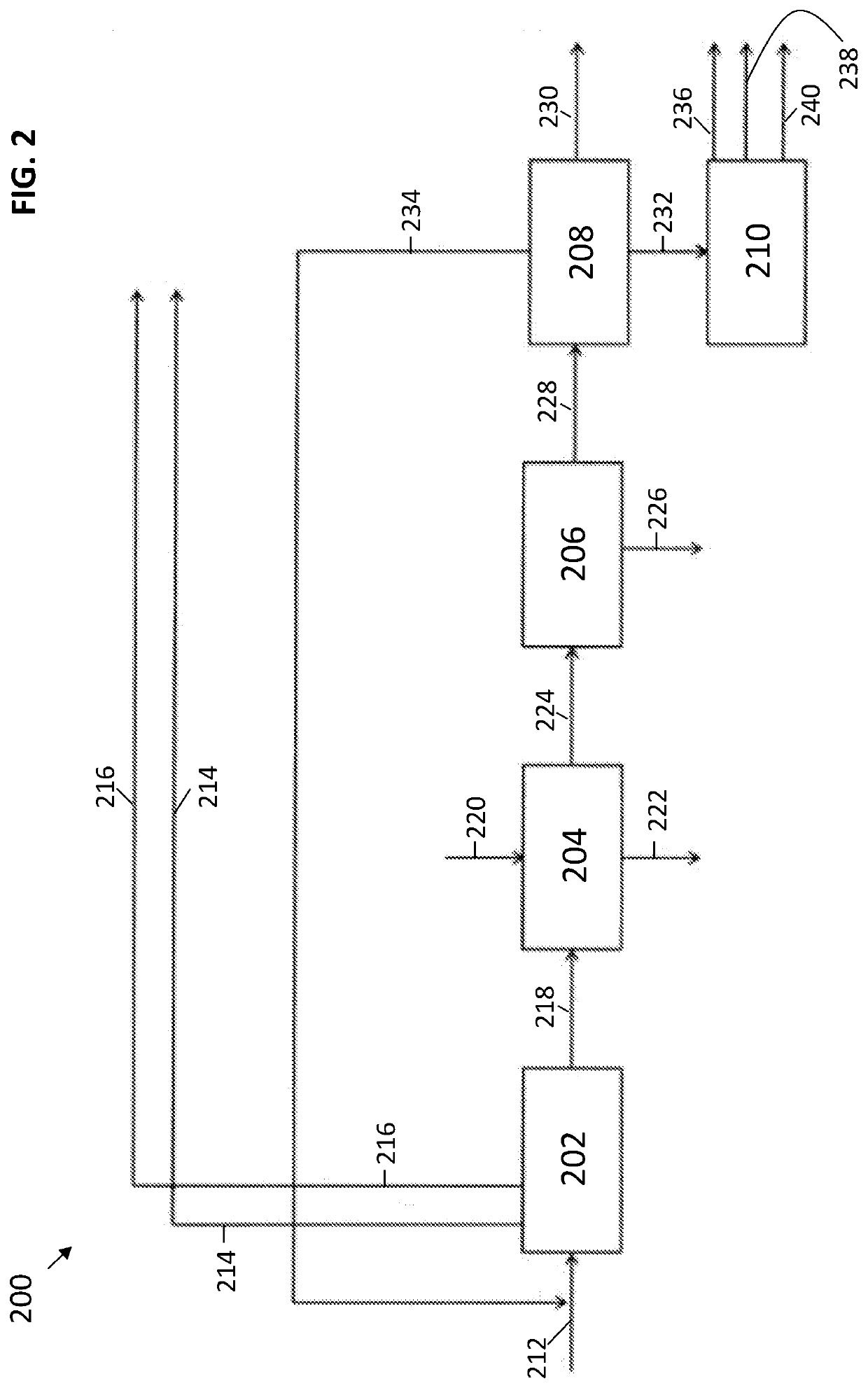
[0073]In this example, a 1000 KTA mixed C4 feed (FIG. 1, conduit 5; FIG. 3, conduit 218) from the steam cracker is used downstream in the subsequent units of the systems FIG. 1 and FIG. 3, respectively. FIG. 6 shows a table displaying the composition of the various streams of the convention system of FIG. 1, FIG. 7 shows a table displaying the composition of the various streams of the system of FIG. 2, and FIG. 8 shows a table displaying the composition of the various streams of the system of FIG. 3 in accordance with one or more embodiments. The tables of FIGS. 6, 7, and 8 are organized by the conduits (lines) shown in FIGS. 1, 2, and 3, respectively.
[0074]As shown in FIGS. 6 and 8, the embodiment of FIG. 3 results in a more than 3-fold increase in isononanol yield as compared with the conventional system of FIG. 1 (FIG. 1, conduit 11: 158 KTA vs. FIG. 2, conduit 230: 558 KTA). Additionally, the embodiment of FIG. 3 also results in a substantial increase in the yield of C8-C16 fuel...
PUM
 Abstract
Description
Claims
Application Information
 - R&D
- Intellectual Property
- Life Sciences
- Materials
- Tech Scout
- Unparalleled Data Quality
- Higher Quality Content
- 60% Fewer Hallucinations
Browse by: Latest US Patents, China's latest patents, Technical Efficacy Thesaurus, Application Domain, Technology Topic, Popular Technical Reports.
© 2025 PatSnap. All rights reserved.Legal|Privacy policy|Modern Slavery Act Transparency Statement|Sitemap|About US| Contact US: help@patsnap.com


