Method for manufacturing a timepiece component and component obtained by this method

Active Publication Date: 2021-08-19
NIVAROX FAR
View PDF0 Cites 0 Cited by
  • Summary
  • Abstract
  • Description
  • Claims
  • Application Information

AI Technical Summary

Benefits of technology

[0018]The purpose of the present invention is to overcome the aforementioned drawbacks and others by providing a method for manufacturing multi-level metal timepiece components using LIGA technology, wherein a co

Problems solved by technology

One drawback of this method is the need to obtain a substantially planar top surface during each galvanic deposition step.
In particular, galvanic growth starts everywhere and the growth fronts join an

Method used


Image

  • Method for manufacturing a timepiece component and component obtained by this method
  • Method for manufacturing a timepiece component and component obtained by this method

Examples


Embodiment Construction

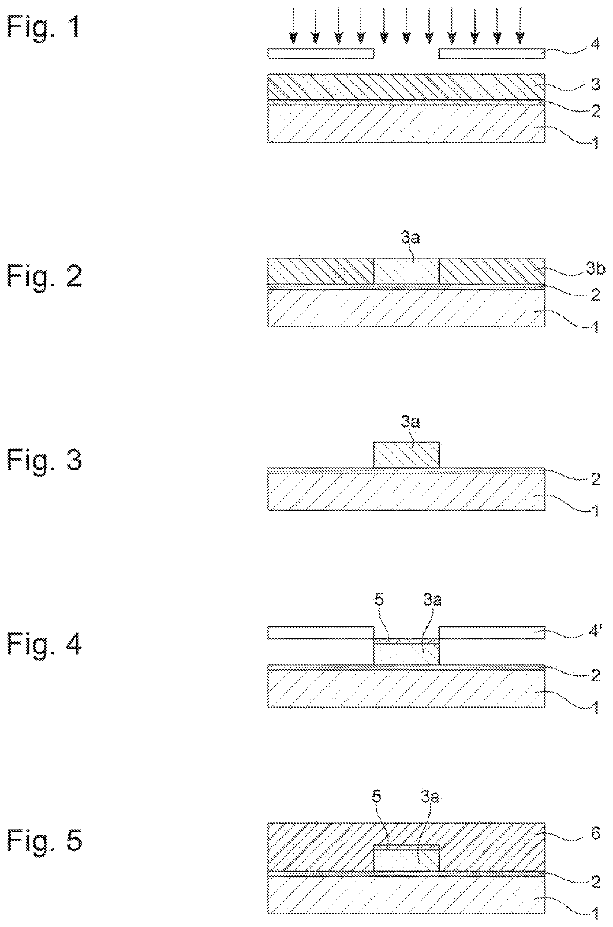
[0044]The substrate 1 used in step a) of the method according to the invention is, for example, formed by a silicon substrate. During the first step a) of the method, a first conductive layer 2, i.e. a layer capable of initiating metal deposition by a galvanic approach, is deposited, for example by physical vapour deposition (PVD). Typically, the first conductive layer 2 is of the Au, Ti, Pt, Ag, Cr or Pd type (FIG. 1), or a stack of at least two of these materials, and has a thickness that lies in the range 50 nm to 500 nm. For example, the first conductive layer 2 can be formed by a chromium or titanium sub-layer covered by a layer of gold or copper.

[0045]The photoresist 3 used in this method is preferably a negative-type octofunctional epoxy-based photoresist available from Microchem under the reference SU-8, designed to polymerise under the effect of UV radiation.

[0046]According to one specific embodiment of the invention, the photoresist takes the form of a dry film, the photor...


PUM

PropertyMeasurementUnit
Thicknessaaaaaaaaaa
Thicknessaaaaaaaaaa
Thicknessaaaaaaaaaa

Abstract

The present invention relates to a method for manufacturing metal timepiece components, characterised in that it comprises the steps of forming a multi-level photoresist mould, by means of a UV-LIGA type method, and of galvanically depositing a layer of at least one metal starting from at least two conductive layers so as to form a block that substantially reaches the top surface of the photoresist.

Description

FIELD OF THE INVENTION[0001]The present invention relates to a method for manufacturing a multi-level metal structure using LIGA technology. The invention further relates to such a metal structure, in particular of timepiece components, obtained by this method.BACKGROUND OF THE INVENTION[0002]Methods that correspond to the above definition are already known. In particular, the article by A. B. Frazier et al. entitled “Metallic Microstructures Fabricated Using Photosensitive Polyimide Electroplating molds” and published in the Journal of Microelectromechanical systems (Vol. 2, N deg. 2, Jun. 1993) describes a method for manufacturing multi-level metal structures by galvanic growth in polyimide moulds produced by the photolithography of photoresist layers. This comprises the following steps of:[0003]creating a sacrificial metal layer and a priming layer on a substrate for a subsequent galvanic growth step,[0004]spreading out a layer of photosensitive polyimide,[0005]irradiating the po...

Claims


Application Information

Patent Timeline
IPC IPC(8): G04D3/00C25D1/00G03F7/00G03F7/16
CPCG04D3/0087C25D1/003G04B15/14G03F7/164G03F7/0035G03F7/00G04B13/02
Inventor GOLFIER, CLARESALIHU, FATMIRCUSIN, PIERRE
Owner NIVAROX FAR
Why Eureka
Try Eureka