
Inductive Power Transmission with Resonant Circuit and Method for Operating the Device

a resonant circuit and power transmission technology, applied in the field of inductive charging, can solve the problems of signal accumulation and interference with one another, and achieve the effect of effective transmission of energy

Active Publication Date: 2021-08-19
BRUSA ELECTRONICS AG
View PDF0 Cites 0 Cited by
  • Summary
  • Abstract
  • Description
  • Claims
  • Application Information

AI Technical Summary

Benefits of technology

The present invention aims to effectively transmit energy and a positioning signal, while preventing interference between preceding and subsequent signals. This can be achieved by dampening emitted signals through a detuned resonant circuit or reducing the quality Q of the resonant circuit during signal transmission. Additionally, the control unit can ensure that the HVDC voltage is present while the positioning signal is being generated to prevent energy from flowing into a battery connected to the output of the HVDC switching circuit.

Problems solved by technology

In the case of excessive resonance at resonance frequencies, signals could build up and interfere with one another.

Method used


Image

  • Inductive Power Transmission with Resonant Circuit and Method for Operating the Device
  • Inductive Power Transmission with Resonant Circuit and Method for Operating the Device

Examples


Embodiment Construction

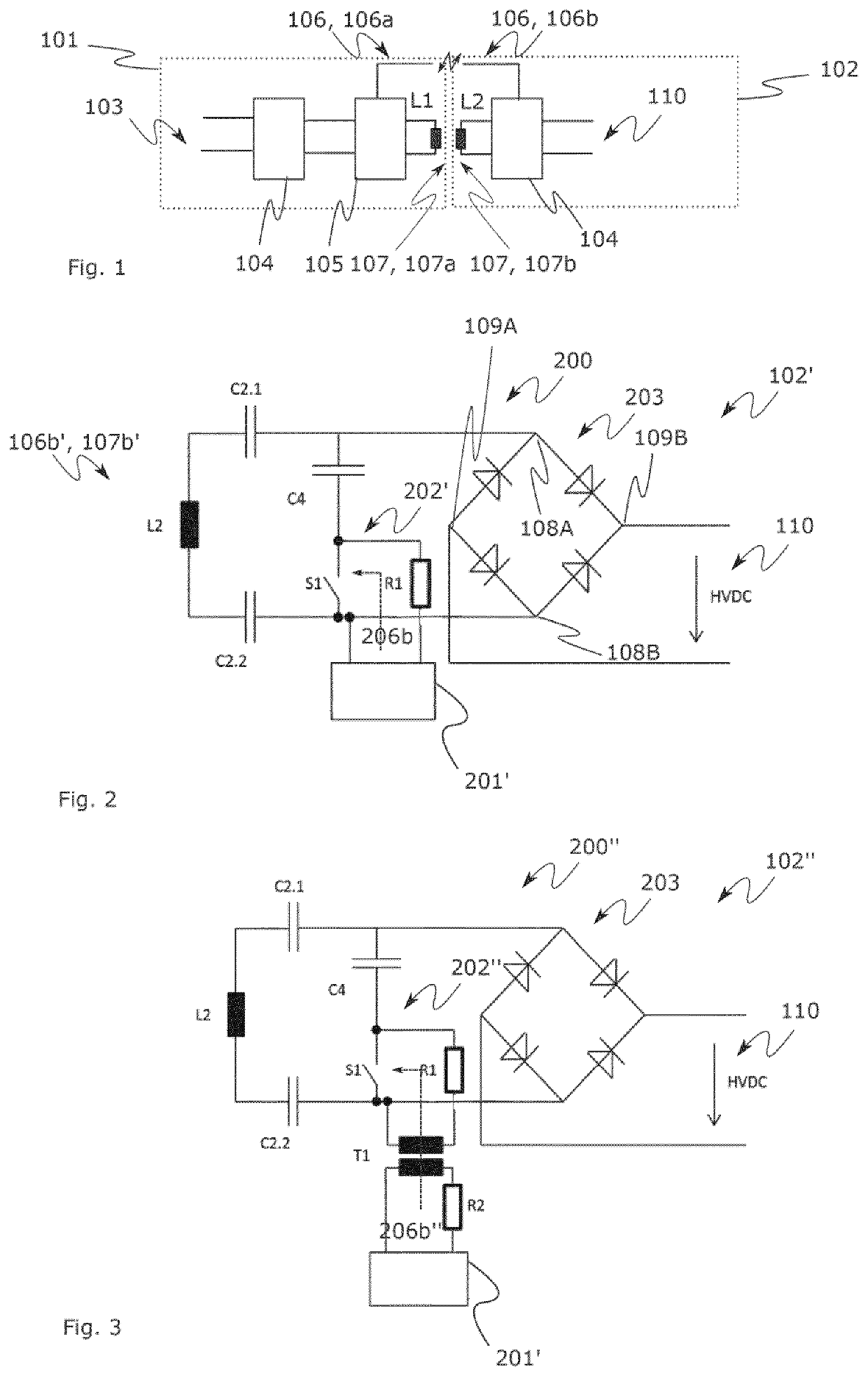
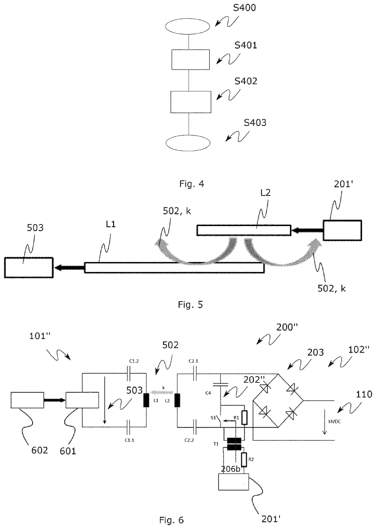
[0041]The representations in the drawings are schematic and not to scale. In the following description of FIGS. 1 to 4, the same reference signs are used for the same or corresponding elements.

[0042]In this text, the terms “capacitor” and “capacitance” as well as “coil” or “choke” and “inductance” should be used synonymously and should not be interpreted restrictively unless otherwise specified.

[0043]FIG. 1 shows a transmission link for inductive charging for a better understanding of the present invention. The transmission link substantially has the stationary ground pad module (GPM) 101 coupled via an air interface and the mobile car pad module (CPM) 102. The main supply is supplied in the form of a voltage via the connection 103. An AC mains voltage with 50 Hz or 60 Hz can be used as the main supply (mains). However, it is also possible to use a DC voltage from a central DC source as mains and only operate the converters locally at 85 kHz for inductive energy transmission.

[0044]T...


PUM


Abstract

The invention relates to an inductive power transmission with a resonant circuit, the resonant circuit including a transmitting / receiving coil or a transmitting and receiving coil for transmitting and / or receiving electromagnetic energy, a coupling capacitor, a tuning capacitor, and a switching device, wherein the switching device is connected in series to the coupling capacitor and the tuning capacitor, and wherein, furthermore, the switching device is designed to activate and / or disconnect a signal generator and to modify a quality factor or to modify the resonance frequency of the resonant circuit.

Description

CROSS-REFERENCE TO RELATED APPLICATIONS[0001]The present application is the U.S. National Phase of PCT / EP2019 / 066650, filed on Jun. 24, 2019, which claims priority to German Patent Application No. 10 2018 115 855.6, filed on Jun. 29, 2018, the entire contents of which are incorporated herein by reference.BACKGROUNDField[0002]The invention relates to the technical field of inductive charging. In particular, the present invention relates to a resonant circuit device and to a method for operating a resonant circuit device.Related Art[0003]A system for inductive energy transmission can be used to electrically charge a purely electric vehicle (EV, electric vehicle) or a hybrid vehicle (PHEV, plug-in hybrid-electric vehicle) that is operated with a combination of fuel and electrical energy, if charging should be done in a contactless manner. In such a system, an alternating magnetic field is generated in the frequency range of 25 kHz-150 kHz. It must be noted that outside this frequency b...

Claims


Application Information

Patent Timeline
Patent Type & Authority Applications(United States)
IPC IPC(8): H02J50/12B60L53/122H04B5/00
CPCH02J50/12H04B5/0075H04B5/0037B60L53/122H02J50/90H02J50/80Y02T10/7072Y02T10/70Y02T90/14H02M7/4818H04B5/24H04B5/79
Inventor HANSELMANN, MARCBÖHLER, LUKASKNUCHEL, RICHARD
Owner BRUSA ELECTRONICS AG
Learn More