Filling apparatus

a technology of filling apparatus and filling chamber, which is applied in the direction of electrochemical generators, container filling under pressure, and discharging methods of containers

Active Publication Date: 2021-09-09
TOKYO TATSUNO CO LTD
View PDF2 Cites 1 Cited by
  • Summary
  • Abstract
  • Description
  • Claims
  • Application Information

AI Technical Summary

Benefits of technology

[0023]Further, when filling is completed in one of the filling systems while filling in a plurality of filling systems, pressure on the fuel gas supply side drops sharply, and there is a risk that the discharge pressure of the filling system that continues filling will fall below the lower limit. However, when the mediation control unit (10C) has a function of transmitting a control signal indicating that filling is finished at a filling system (for example, the filling system 1A on the side A) to another filling system that continues filling (for example, the control unit 10B on the side B), and the control unit of the filling system that continues filling (for example, the control unit 10B on the side B) has a function of transmitting a control signal for increasing pressure of the filling system (for example, for increasing the opening degree of the flow rate adjusting valve 2B) when receiving the control signal indicating that the filling is completed at the other side filling system (for example, the filling system 1A on the side A) via the mediation control unit (10C), it is prevented that the discharge pressure of the filling system (for example, the filling system 1B on the side B) that continues filling may fall below the lower limit.

Problems solved by technology

Therefore, immediately after the start of hydrogen filling, the required pressure drops very significantly (for example, the pressure is lowered by 50 MPa), which causes a problem that a large load is applied to the rear facility.

Method used


Image

  • Filling apparatus
  • Filling apparatus
  • Filling apparatus

Examples


first embodiment

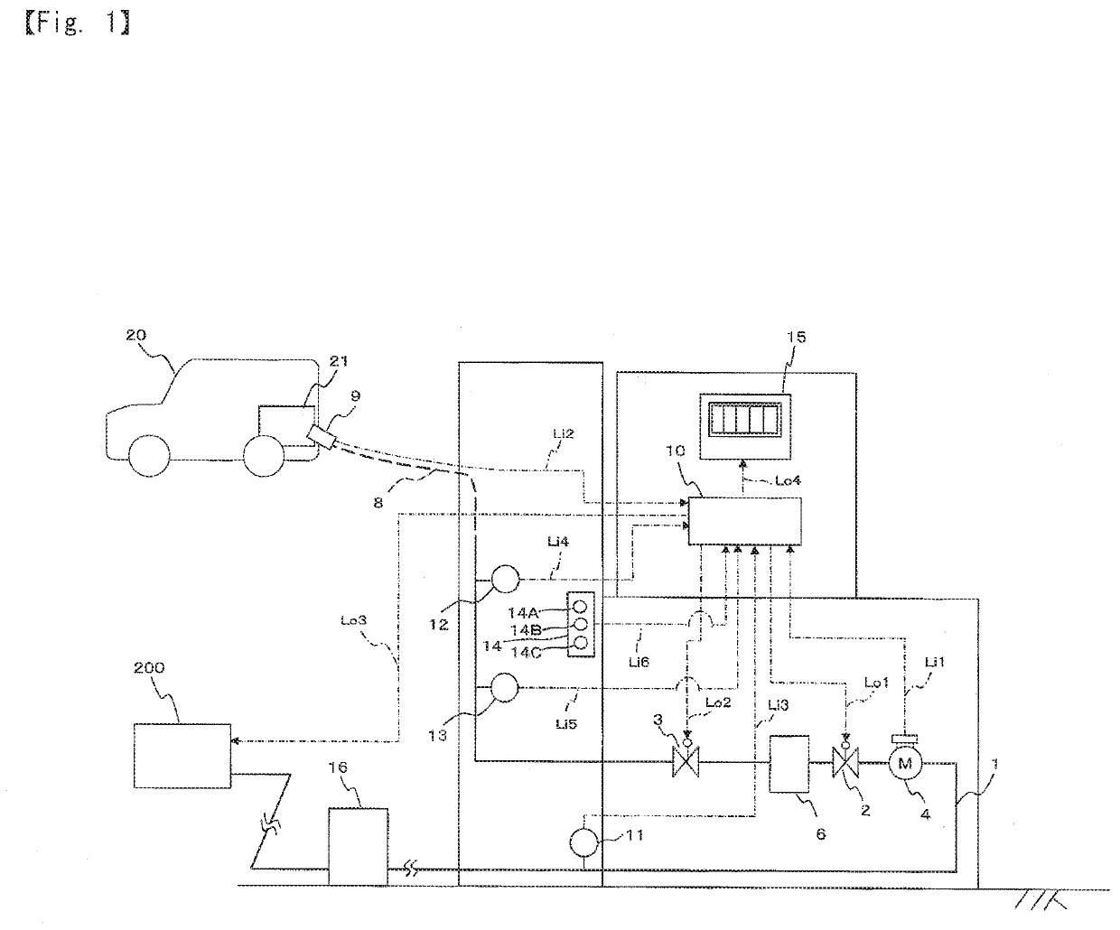
[0031]Hereinafter, embodiments of the present invention will be described with reference to the accompanying drawings. In the illustrated embodiments, a case where a gas to be filled is hydrogen is shown, but the filling apparatus according to the illustrated embodiments can also be applied to filling of other gases. First, the present invention will be described with reference to FIGS. 1 and 2. In FIG. 1, the filling apparatus represented by the reference numeral 100 includes a hydrogen supply pipe 1, a flow meter 4, a flow rate adjusting valve 2 (pressure adjusting valve), a cooling unit 6 (gas pipeline cooling unit), a shutoff valve 3, and a control unit 10. An upstream side of the hydrogen supply pipe 1 is connected to a hydrogen gas supply source 200 (rear facility, primary side) via an accumulator 16, and a downstream side of the hydrogen supply pipe 1 is connected to a vehicle-side tank 21 of a vehicle 20 (fuel cell vehicle) via a filling hose 8 and a filling nozzle 9 (FIG. 1...

second embodiment

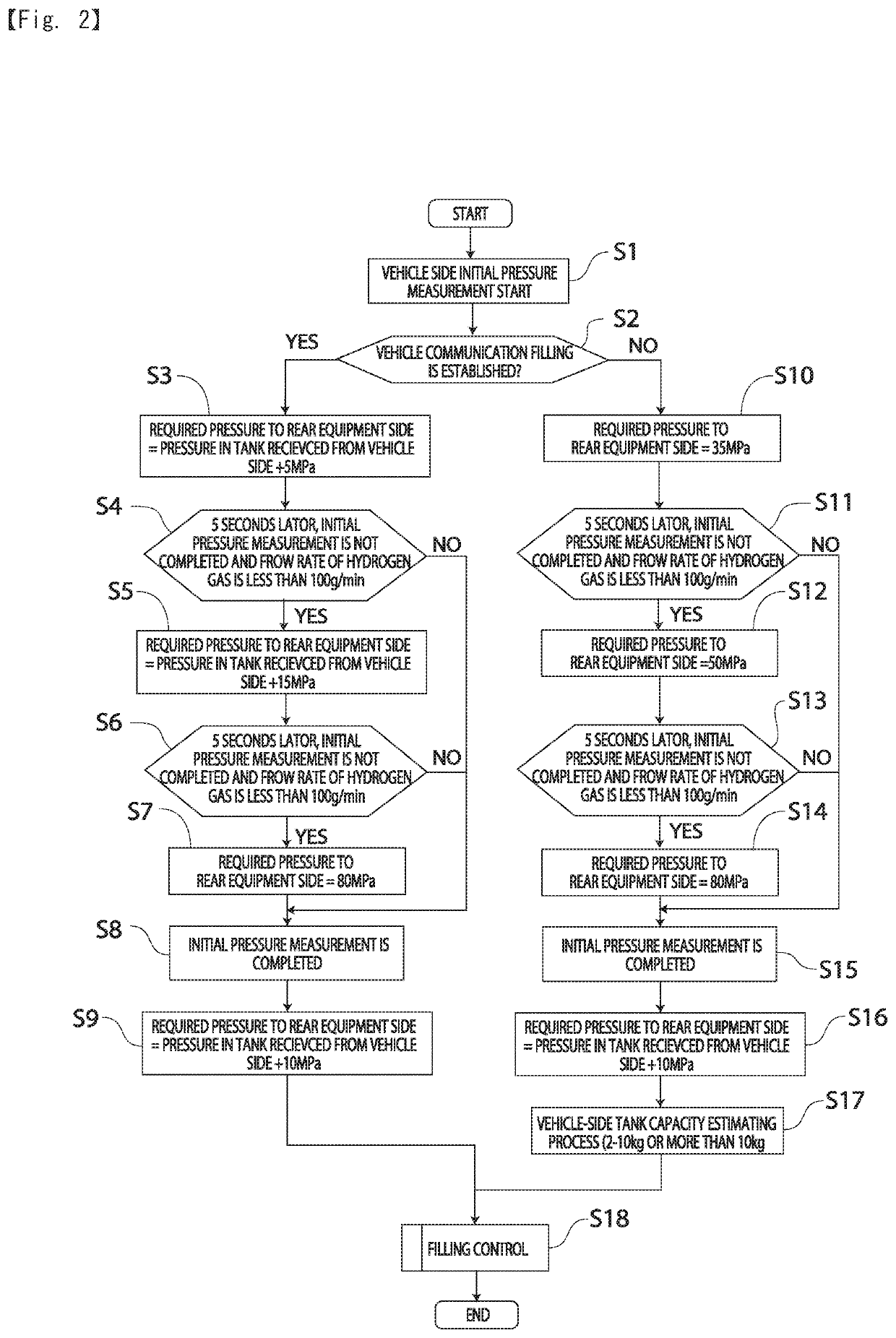
[0050]In step S15, the measurement of the initial pressure is completed, and the process proceeds to step S16. In step S16, the required pressure to the rear facility 200 is set higher than the measured initial pressure by, for example, 10 MPa (constant pressure). Then, the process proceeds to step S17. In step S17, a process of estimating capacity of the vehicle-side tank 21 (for example, a process of determining whether mass capacity of the vehicle-side tank 21 is in a range of 2 to 10 kg or exceeds 10 kg) is executed. Since communication filling has not been established in step S17, such processing is required. After executing the tank capacity estimation process, the process proceeds to step S18. In step S18, filling control is executed. Specific control procedure of the filling control will be described later with reference to the flowchart of FIG. 7 regarding the

[0051]With the first embodiment shown in FIGS. 1 and 2, pressure required from the control unit 10 (hydrogen filling...


PUM


Abstract

A filling apparatus that does not significantly reduce a required pressure immediately after a start of hydrogen filling, and can reliably fill fuel cell vehicles and the like. The filling apparatus (100) of the present invention includes a control unit (10), and the control unit (10) has a function of boosting pressure required from a hydrogen filling apparatus (100) to a rear facility (200) until initial pressure measurement is completed. The control unit (10) may have a function of determining whether or not communication filling is established, and when communication filling is established, setting a pressure higher than an internal pressure of a tank received from a vehicle side by a predetermined pressure (for example, 5 MPa) as a pressure required for the rear facility (200) at an initial stage of filling.

Description

CROSS-REFERENCE TO RELATED APPLICATIONS[0001]The present application claims priority to Japanese Patent Application No. 2020-035495 filed on Mar. 3, 2020, the disclosure of which is incorporated herein by reference.STATEMENT RE: FEDERALLY SPONSORED RESEARCH / DEVELOPMENT[0002]Not ApplicableBACKGROUND1. Field of the Invention[0003]The present invention relates to a filling apparatus for filling a fuel gas such as hydrogen gas.2. Description of the Related Art[0004]In recent years, with development and popularization of vehicles equipped with fuel cells (fuel cell vehicles: FCVs), it has become important to increase the number of hydrogen stations (see, for example, Japanese Patent Publication No. 2000-166635 gazette). The hydrogen station is provided with a hydrogen filling apparatus, and the apparatus fills an in-vehicle tank of a vehicle arriving at the hydrogen station with hydrogen within a predetermined pressure range.[0005]Conventionally, when a fuel cell vehicle is filled with h...

Claims


Application Information

Patent Timeline
Patent Type & Authority Applications(United States)
IPC IPC(8): F17C5/00F17C13/02
CPCF17C5/007F17C13/025F17C2221/012F17C2250/032F17C2270/0184F17C2270/0168F17C2265/065F17C2250/043F17C2250/0443F17C2250/0626F17C5/06F17C13/02F17D3/01F17C2225/036F17C2205/0326F17C2223/0123F17C2223/036F17C2223/035F17C2225/0123F17C2227/0157F17C2227/0337F17C2205/0364F17C2227/04F17C2250/034F17C2250/0439F17C2250/0636F17C2260/021F17C2260/02F17C2270/0139Y02E60/32
Inventor YOSHIDA, YUICHI
Owner TOKYO TATSUNO CO LTD
Why Eureka
Try Eureka