
Implantable scaffolds and uses thereof

a technology of implants and scaffolds, applied in the field of implants, can solve the problems of difficult treatment, large size of tissue defects, and inability to heal naturally

Pending Publication Date: 2021-09-30
NANOCHON LLC
View PDF5 Cites 4 Cited by
  • Summary
  • Abstract
  • Description
  • Claims
  • Application Information

AI Technical Summary

Benefits of technology

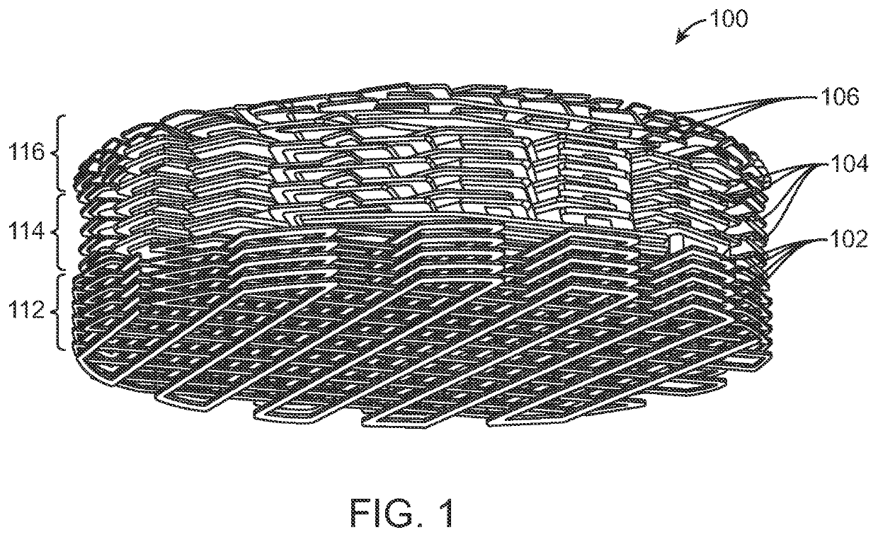
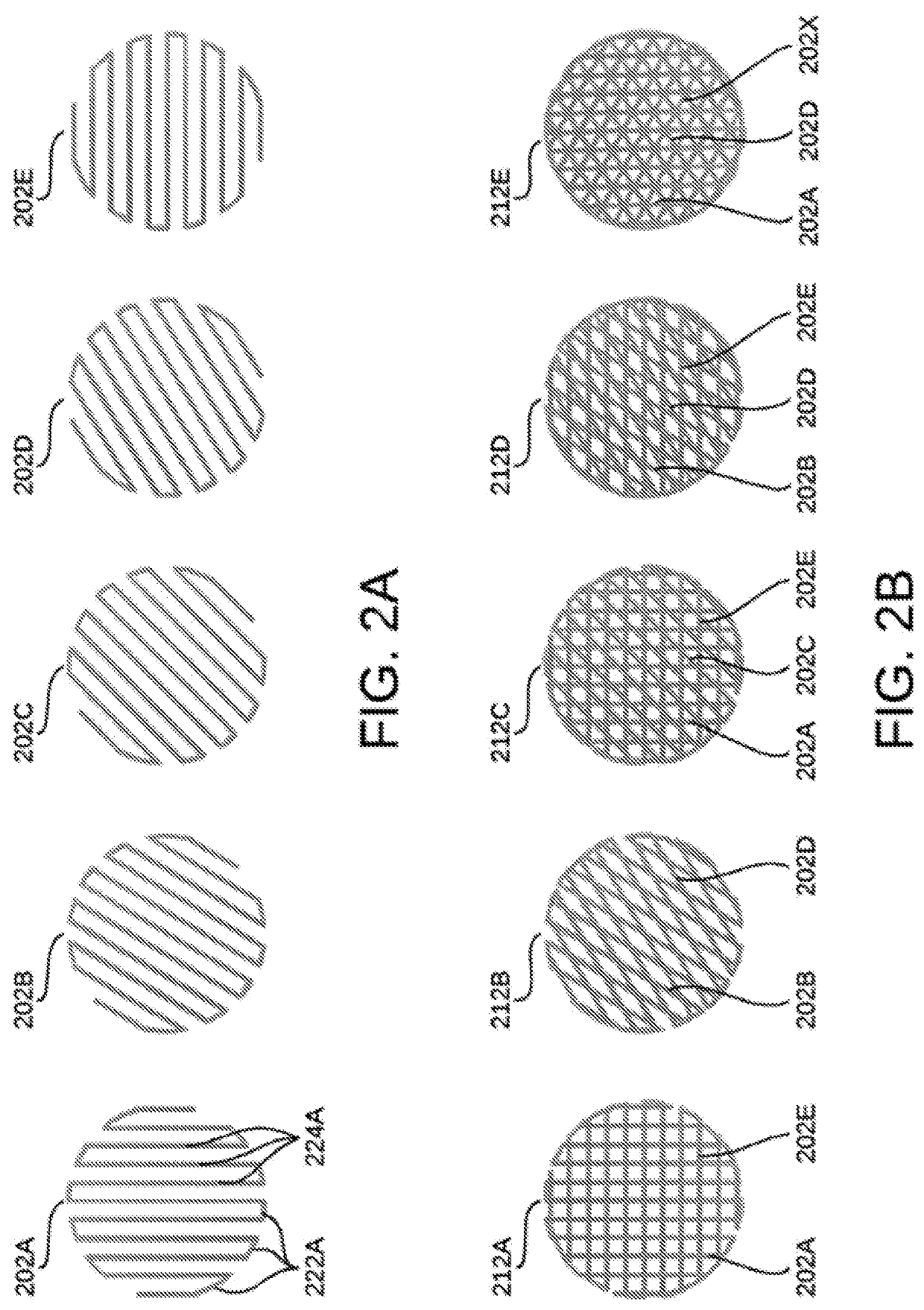
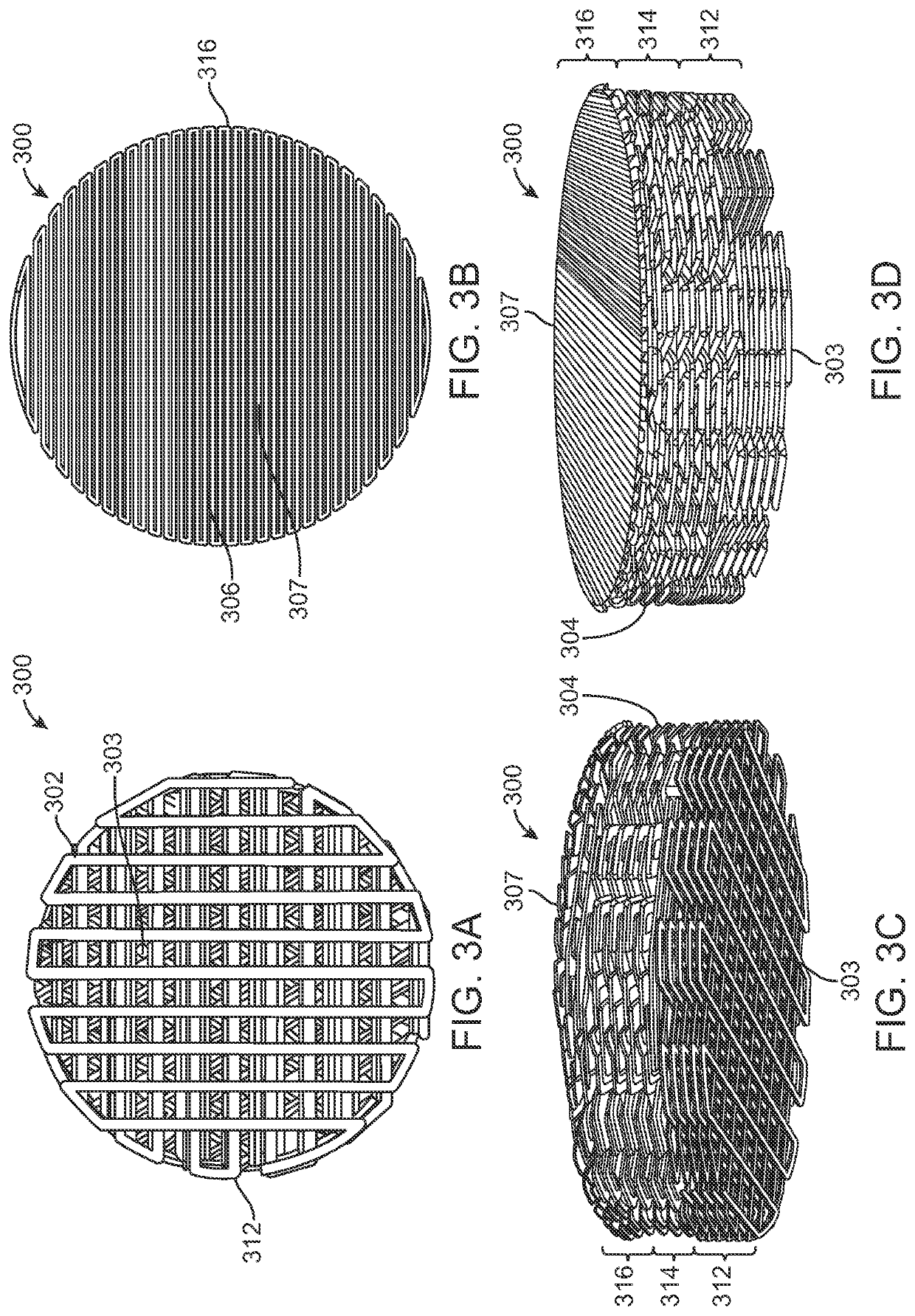
The patent describes a method for making a three-dimensional scaffold that can be used to promote bone regeneration, vascular regeneration, cartilage regeneration, or a combination of these at tissue regions such as osteochondral regions. The scaffold is made up of layers that have a specific pattern and can be designed to mimic the natural structure of the tissue. The scaffold can be made using a 3D printing process. The technical effect of this patent is to provide a better understanding of the factors that promote bone and tissue regeneration, and to provide a more effective scaffold for promoting bone and tissue regeneration at specific regions of the body.

Problems solved by technology

Large, critical-sized tissue defects (e.g., those that are too large to heal naturally) caused by traumatic injury, cancer, or disease of tissue may be challenging to treat.
These defects may often be associated with a low rate of recovery and high patient morbidity.

Method used


Image

  • Implantable scaffolds and uses thereof
  • Implantable scaffolds and uses thereof
  • Implantable scaffolds and uses thereof

Examples


example 1

ion of a Scaffold

[0184]Reference is now made to FIG. 8, which depicts a non-limiting example of a procedure 800 for implanting a tissue engineering scaffold arthroscopically into an osteochondral defect according to one or more aspects of the present disclosure.

[0185]At step 802, an arthroscopic entry may be made into the tissue defect area. In some instances, the tissue defect area may comprise a bone and / or cartilage defect to the knee. In other instances, the defect area may be a defect to any osteochondral interface in the body.

[0186]At step 804, the defect area may be cleaned and prepped for application of surgical techniques, as well as a tissue scaffold as described herein. Specifically, in the event that the tissue defect includes damage to cartilage at the site of arthroscopic entry, the cartilage area in and around the defect area may be cleaned, thereby exposing the underlying bone surface.

[0187]At step 806, a microfracture surgical technique may be applied to the defect ...

example 2

and Mechanical Studies

[0195]In vitro studies were carried out to characterize the response of mesenchymal stem cells (e.g., MSCs) in relation to a 3D printed nanoporous thermoplastic polyurethane (e.g., nTPU) tissue engineering scaffold. Previous studies in vitro and in vivo suggested that the 3D printed nanoporous nTPU scaffold was osteogenic and promoted vascularization, both of which are required for healthy attachment to bone in a clinical setting. Thus, additional in vitro testing focused on confirming and expanding on this observed effect on an implant designed to replace lost or damaged cartilage on the articulating surface of the knee. In preparation for further in vitro testing, 3D porous bi-phasic disks were designed, 3D printed, sterilized, and subsequently evaluated via MSC cell study, assays, confocal imaging, and quantitative analysis. Additionally, mechanical testing studies were performed, including both compression and fatigue tests, and SEM images of the fatigued s...

example 3

ring Analysis

[0201]During manufacturing analysis, the printability of nTPU was assessed across a two-phase approach. In the first phase, the first step was to perform small scale lab tests which were followed by an assessment and decision to go forward to phase two with actual print tests.

[0202]By choosing specific test artifacts, the various barriers between a new material and processability via various rapid prototyping methods were assessed. Three different categories of artifacts or parts were produced: parameter setting, part / design properties, and actual geometries.

[0203]The manufacturing feasibility conducted during manufacturing analysis had several objectives. First, to evaluate the printability of nTPU across various rapid prototyping methods. For example, in regard to the rapid prototyping method of selective laser sintering (e.g., SLS), small scale labs tests that the material had to clear were SSC analysis to determine a thermal printing window, TGA analysis to show mat...


PUM

PropertyMeasurementUnit
sizeaaaaaaaaaa
sizeaaaaaaaaaa
sizeaaaaaaaaaa

Abstract

The present disclosure relates to a three-dimensionally (e.g., 3D) printed, surgically implantable tissue engineering scaffolds for promoting bone, vascular, and / or cartilage regeneration at osteochondral regions and a method for manufacturing the 3D printed surgically implantable tissue engineering scaffold. The 3D printed surgically implantable tissue engineering scaffold may be fabricated at least in part from a thermoplastic polyurethane (e.g., nTPU) composite via a rapid prototyping machine. In some cases, the three-dimensional shape of the fabricated tissue engineering scaffold may correspond to a three-dimensional shape of a tissue defect of a patient.

Description

CROSS-REFERENCE[0001]This application claims the benefit of U.S. Provisional Application No. 62 / 711,667, filed Jul. 30, 2018, and U.S. Provisional Application No. 62 / 775,228, filed Dec. 4, 2018, each of which is entirely incorporated herein by reference.BACKGROUND[0002]Large, critical-sized tissue defects (e.g., those that are too large to heal naturally) caused by traumatic injury, cancer, or disease of tissue may be challenging to treat. These defects may often be associated with a low rate of recovery and high patient morbidity. Developing scaffolds may address this need.BRIEF SUMMARY[0003]The following presents a simplified summary of various aspects described herein. This summary is not an extensive overview, and is not intended to identify key or critical elements or to delineate the scope of the claims. The following summary merely presents some concepts in a simplified form as an introductory prelude to the more detailed description provided below.[0004]Provided herein are s...

Claims


Application Information

Patent Timeline
Patent Type & Authority Applications(United States)
IPC IPC(8): A61F2/30
CPCA61F2/30771A61F2002/3093A61F2002/3092A61F2002/30784A61F2002/30985A61F2002/30971A61F2002/3084A61F2002/30766A61L27/56B33Y70/00B33Y80/00A61F2/2846A61F2/30756A61F2/30749A61F2002/285A61F2002/30011A61F2002/30751A61F2002/30136
Inventor HOLMES, BENJAMINCASTRO, NATHAN
Owner NANOCHON LLC
Learn More