
Roller-membrane layering micro stereolithography

a micro-sequencing and micro-sequencing technology, applied in the direction of additive manufacturing processes, manufacturing tools, manufacturing data acquisition/processing, etc., can solve the problems of poor method for defining 10 um or thinner resin layers, still impractically slow, etc., to achieve greater speed and accuracy in layer thickness, maintain the dimensional accuracy of samples printed, and improve the effect of control

Pending Publication Date: 2021-09-30
BMF NANO MATERIAL TECH CO LTD
View PDF8 Cites 3 Cited by
  • Summary
  • Abstract
  • Description
  • Claims
  • Application Information

AI Technical Summary

Benefits of technology

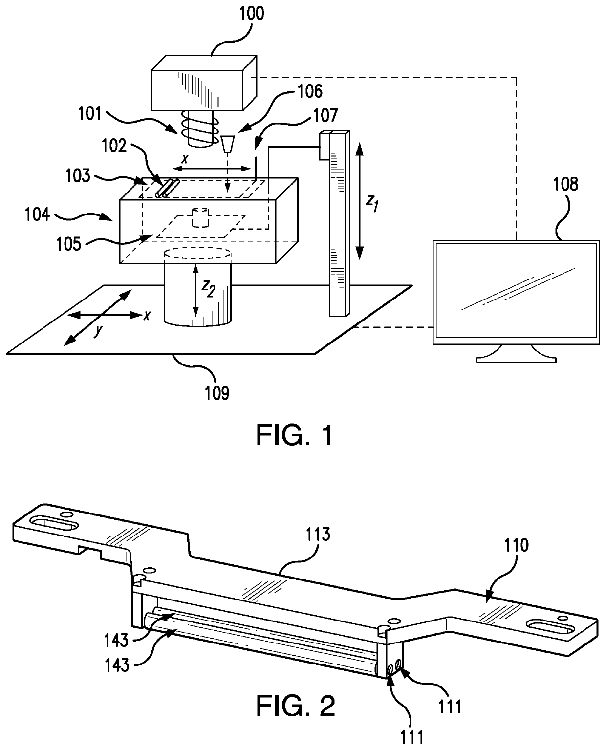
The present invention is a method of layered printing that provides greater speed and accuracy in controlling the thickness of layers in a larger printing area, such as a 10 cm×10 cm printing area with 5-20 um layer thickness. The method uses a dual-roller spreader combined with a clear membrane, which improves the printing speed while maintaining the dimensional accuracy of samples printed using PμSL systems. The roller spreader has at least one roller made of metal or ceramic for rigidity and accuracy, and an optically clear membrane of 50 um to 100 um thick isolates the rollers from the printing material. The invention is not limited to a linear spreader that oscillates in a single direction, but can also be designed as a rotary spreader with differential mechanism.

Problems solved by technology

Again, for both cases, as for the first method previously described, there is currently no good method for defining 10 um or thinner resin layers over an area of 5 cm×5 cm or larger, especially for the membrane case, because even if it is faster than the free surface case, it is still impractically slow.

Method used


Image

  • Roller-membrane layering micro stereolithography
  • Roller-membrane layering micro stereolithography
  • Roller-membrane layering micro stereolithography

Examples


Embodiment Construction

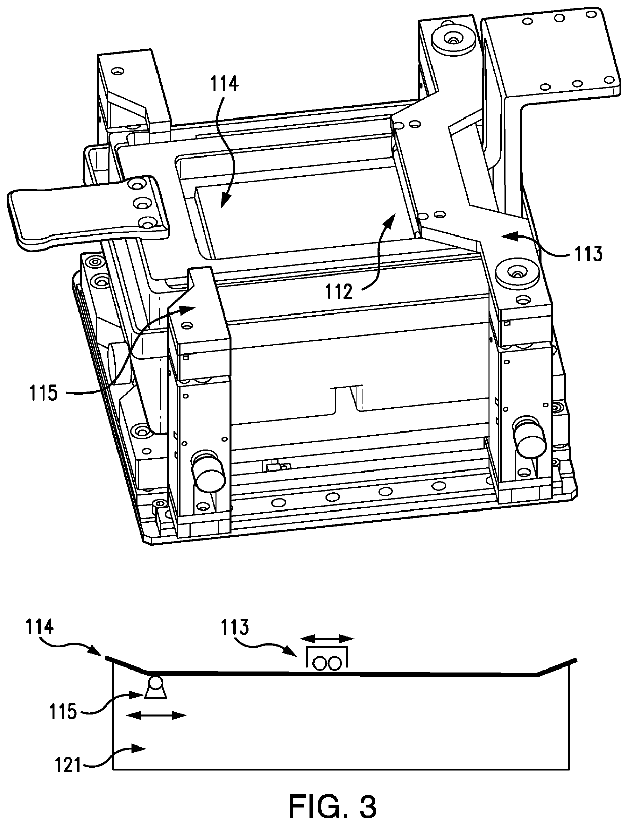
[0024]In one embodiment of the invention, the method is aided by a dual-roller spreader as in FIG. 2, e.g., as part of the light engine / spreader / membrane / displacement system discussed above. Rollers can be made of metals or ceramic to maintain rigidity during the rolling and spreading process on the membrane. At the same time the metal or ceramic helps to hold the precise tolerance (less than 10 um) on the dimensions. Dual rollers having a diameter of 6 mm with a gap of 500 um and 104 mm long can be used to cover a 100 mm×100 mm printing area. Metals or ceramics are much harder than the membrane, usually PFA (PerFluoroAlkoxy) or FEP (Polyfluoroethylenepropylene), therefore the rollers can cause damage to the surface, and thus reduce the optical clarity, i.e., optical transparency, of the membrane. To protect the membrane surface during the frequent rolling steps, the outer diameter of the roller is covered with a silicone or rubber skin of 50 um-100 um thick. The protective skin is ...


PUM

PropertyMeasurementUnit
displacementaaaaaaaaaa
thickaaaaaaaaaa
thicknessaaaaaaaaaa

Abstract

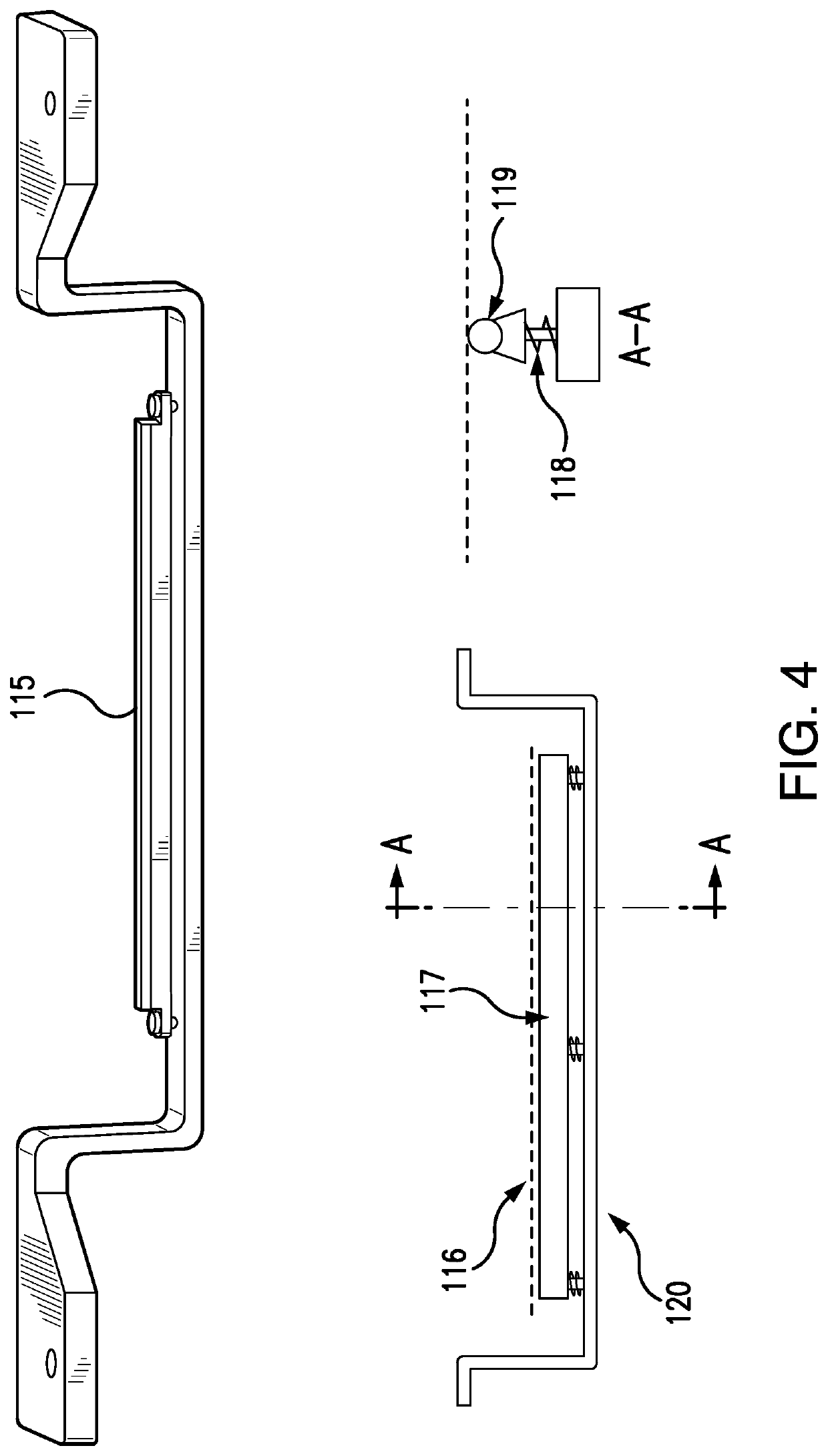
The speed and control over layer thickness in multi-layer 3-D printing is enhanced when producing a sample layer by projecting an image of the layer from light engine onto an optically clear membrane in contact with a printing material to prepare a sample layer in contact with the membrane, followed by moving the sample away from the membrane to separate the two, then moving the sample back toward the membrane to a point where the distance between the membrane and sample, as measured by a laser displacement sensor, is equal to the thickness of the next layer. While the sample moves back toward the membrane a dual-roller spreader or rotary roller spreader oscillates on the membrane to simultaneously to drive away printing material and flatten the membrane. A bubble scrapper is employed to remove bubbles from the printing material as they form.

Description

[0001]The present invention provides an improved method for faster printing over a larger-area with printing materials of a broader viscosity range, e.g., typically light curable resins have a viscosity up to 30,000 cPs, without sacrificing the resolution available from existing micro stereolithography methods, a 3D printing technology. For example, many present embodiments combine a dual-roller spreader with an optically clear, i.e., optically transparent, membrane, which quickly defines a very thin layer of printing materials, e.g., resins, during large-area printing. The method of the invention disclosed herein is not limited to projection type of micro 3D printing methods using DLP or LCD; it is also valid for any other type of method using laser beam / spot scanning to define the shape of solid layer in 3D printing.BACKGROUND OF THE INVENTION[0002]Stereolithography was originally conceived as a rapid prototyping technology. Rapid prototyping refers to a family of technologies tha...

Claims


Application Information

Patent Timeline
Patent Type & Authority Applications(United States)
IPC IPC(8): B29C64/135B33Y10/00B33Y30/00B33Y50/02B29C64/393B29C64/264B29C64/218B29C64/245
CPCB29C64/135B33Y10/00B33Y30/00B29C64/245B29C64/393B29C64/264B29C64/218B33Y50/02B29C64/124B29C64/194
Inventor XIA, CHUNGUANGFU, LIANGKANG
Owner BMF NANO MATERIAL TECH CO LTD
Learn More