Liner Support System

a support system and liner technology, applied in the direction of machines/engines, sustainable transportation, climate sustainability, etc., can solve the problems of complex systems and complex systems of hangers, and achieve the effects of reducing the net load of cmc liner, reducing the load, and reducing the number of hangers or supports

Pending Publication Date: 2021-10-07
GENERAL ELECTRIC CO
View PDF6 Cites 2 Cited by
  • Summary
  • Abstract
  • Description
  • Claims
  • Application Information

AI Technical Summary

Benefits of technology

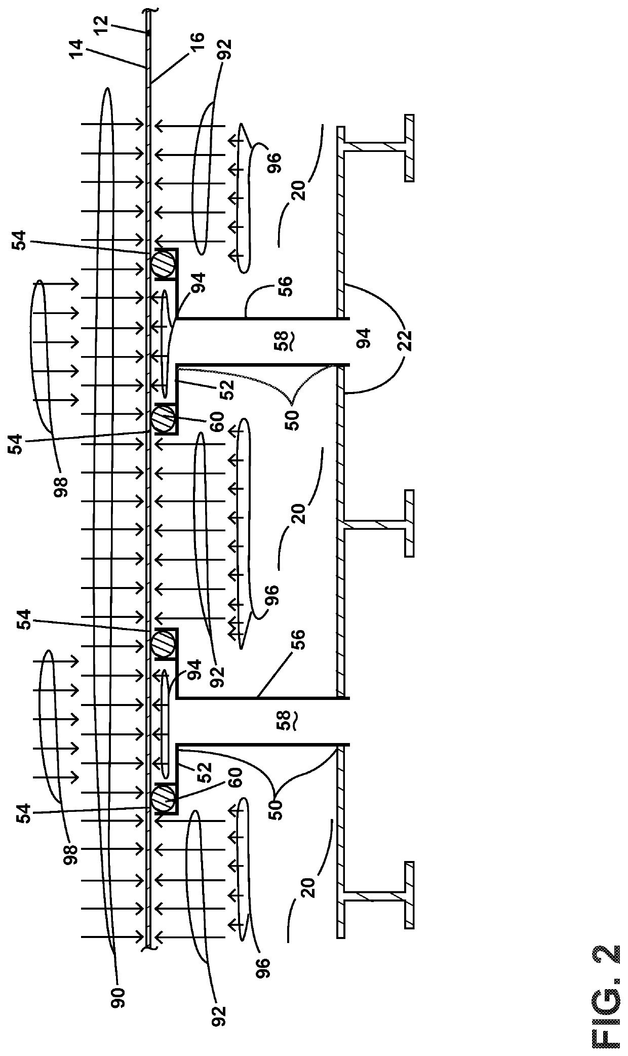
[0006]The present invention advantageously utilizes a CMC liner as a substitute for a metallic (superalloy) liner. In the present invention, the net load on the CMC liner is reduced by a system of delta pressure regions alternating the load incrementally along the liner surface. The alternating delta pressure regions reduce the load, allowing a reduction in the number of hangers or supports required to mount the liner to the duct.

Problems solved by technology

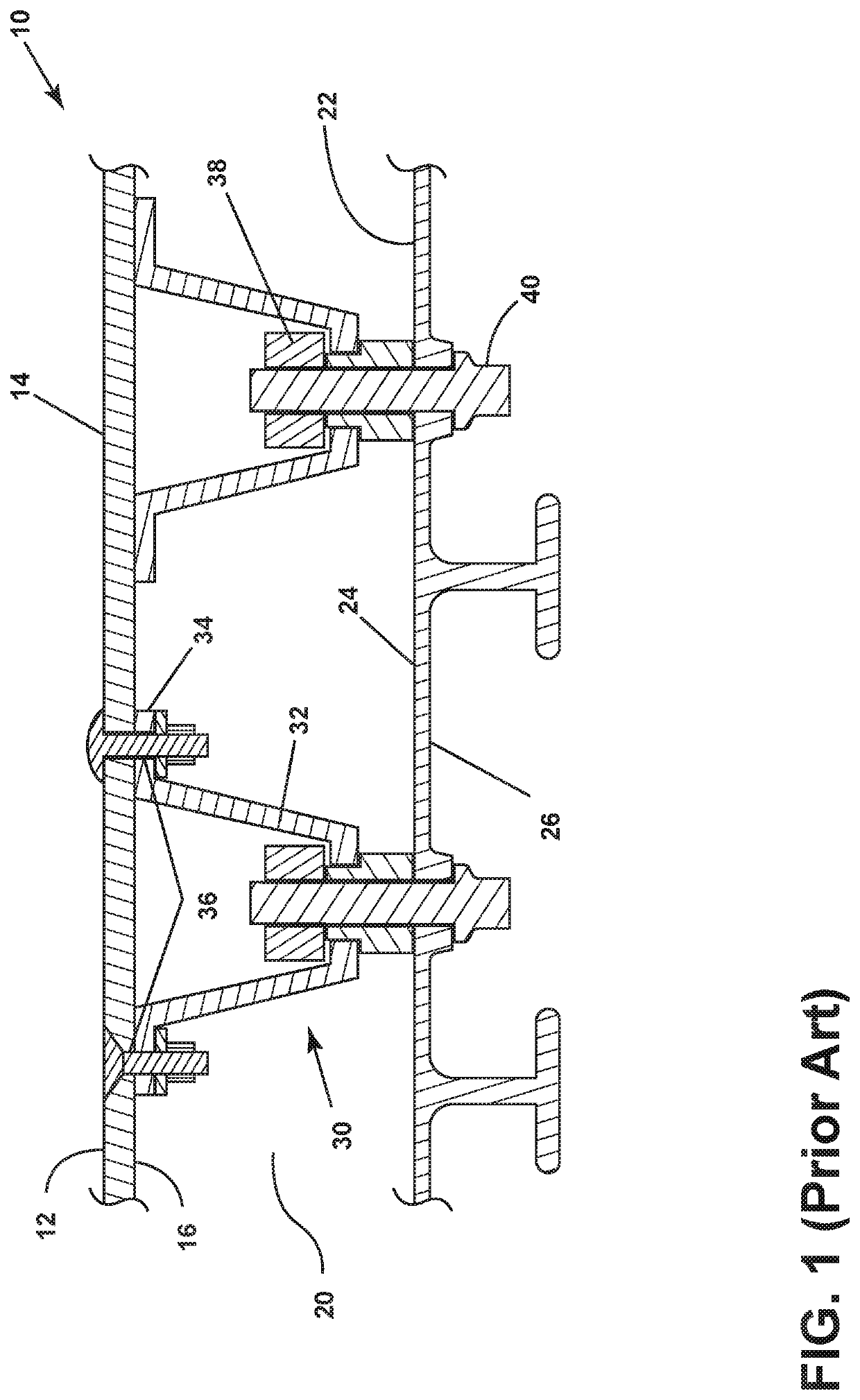
Exhaust systems are complex structures and generally comprise an exhaust liner mounted within an exhaust duct.
The hanger systems are complex systems and have typically been made of superalloys or other high strength materials.
However, liners comprising these CMC materials still must be mounted to the engine duct.

Method used


Image

  • Liner Support System
  • Liner Support System
  • Liner Support System

Examples


second embodiment

[0034]FIG. 5 is the present invention in which the post provides a pattern of alternating or reversed pressures, but the post does not support the liner. Depicted in cross section is a post 50 with a face seal 159 in a floating seal ring 160, the post spacing exhaust liner 12 from exhaust duct 22 and extending through the duct. When the engine is in operation, a sink pressure in the direction of duct 22 is created in interface region 52. In this embodiment, face seal 159 interfaces with back side 16 of exhaust liner, preventing leakage of fan air from annulus 20 and into post passageway 58. Fan air pressure urges floating seal ring 160 upward which contacts face seal 159 against back side of exhaust liner when the engine is operating. Radial seal 162 exerts a radial force against the floating seal ring 160, the seal being housed in a groove in post 50 and thereby sealing the seal ring to post 50, preventing fan air from entering sink interface region 52.

[0035]Also shown in FIG. 5 is...

third embodiment

[0036]FIG. 6 is the present invention, wherein the post provides a region of reverse pressure load. In this arrangement, the post can support the liner and the post can accommodate tilting of the liner during operation. In FIG. 6, there is depicted the angle-conforming load-reacting post 50 for interfacing with a contoured exhaust liner 112 having flat areas 170, such as depicted by the exhaust liner 112 depicted in FIG. 4. Liner 112 also may be contoured without flat areas 170. Post 50 having periphery with a spherical interface 154 having a predetermined geometry is in contact with cup 172. As shown in FIG. 6, the spherical interface has a concave shape facing back side 16 of liner 12, the back side of liner 12 also having a predetermined geometry, shown in FIG. 4 as flat areas 170. The preselected geometries of the periphery, spherical interface forming cup 172, includes both a concave geometry and a convex geometry. The preselected geometries of liner 12 mating with periphery 15...


PUM


Abstract

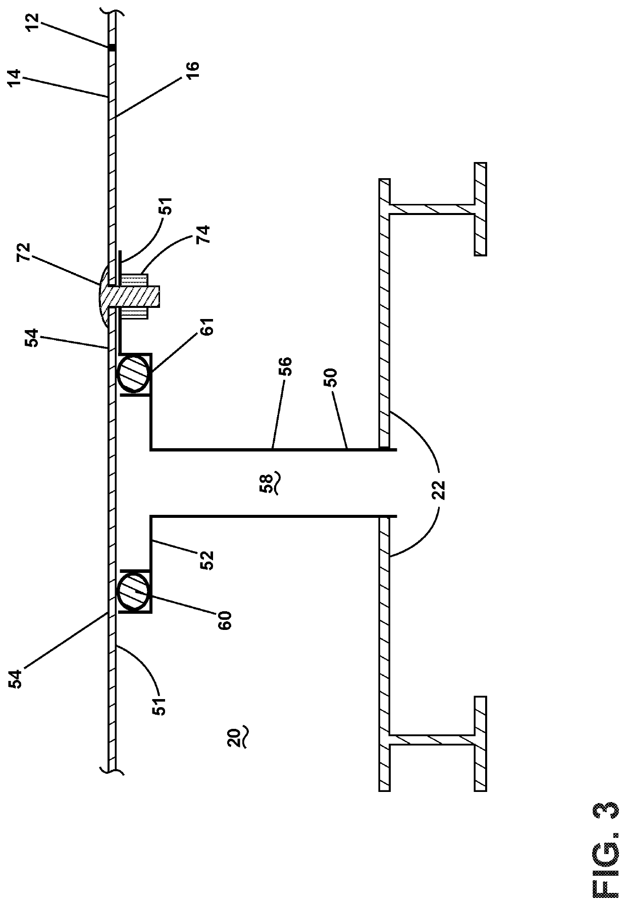
A liner support system for an exhaust liner in an aircraft engine. The liner support system includes a plurality of posts that space the exhaust liner from the exhaust duct, the plurality of posts spacing the exhaust liner from the exhaust duct further supporting the exhaust liner. Each post includes an interface region adjacent to the back side of the exhaust liner sealed to the back side of the exhaust liner, a shank extending to a low pressure region, and a hollow passageway internal to the shank, providing fluid communication between the interface region and the low pressure region. The low pressure region results in pressure against the liner, pulling the liner adjacent the post interface region against the post while preventing fluid leakage between the exhaust liner and the interface region. The posts create a pattern of alternating pressures in the liner allowing for elimination of hangers.

Description

FIELD OF THE INVENTION[0001]The present invention is generally directed to a liner support system, and specifically to a liner support system for CMC exhaust liners.BACKGROUND OF THE INVENTION[0002]Exhaust systems in aircraft engines are conduits for gases from combustion passing through the turbine section. These hot gases, after passing through the turbine section and into the exhaust section, are referred to as exhaust gases and are used to provide thrust to propel the aircraft.[0003]Exhaust systems are complex structures and generally comprise an exhaust liner mounted within an exhaust duct. The exhaust duct(s) in modern aircraft is / are housed within the airframe of the aircraft in an engine bay. The exhaust duct is mounted within the engine bay using conventional methods.[0004]The exhaust liner is mounted within the exhaust duct. The exhaust liner is spaced from the exhaust duct and held in place within the exhaust liner by hanger systems. The hanger systems are complex systems...

Claims


Application Information

Patent Timeline
Patent Type & Authority Applications(United States)
IPC IPC(8): F01D25/30F01D25/00F01D25/14
CPCF01D25/30F01D25/005F01D25/14F05D2260/20F05D2260/31F05D2300/6033F05D2240/14F05D2220/323F01D25/00Y02T50/60
Inventor CORSMEIER, DONALD MICHAELRENGGLI, BERNARD JAMESBONNER, KURT J.
Owner GENERAL ELECTRIC CO
Why Eureka
Try Eureka