Lithium composite oxide sintered body plate

a lithium composite oxide and body plate technology, applied in the field of lithium composite oxide sintered body plate, can solve the problems of large voltage drop, large amount of gas generated, and inability to obtain sufficient voltage to drive the circuit, etc., to suppress gas generation, reduce reaction resistance, and excellent quick charging performance and cycle performance

Inactive Publication Date: 2021-10-28
NGK INSULATORS LTD
View PDF0 Cites 0 Cited by
  • Summary
  • Abstract
  • Description
  • Claims
  • Application Information

AI Technical Summary

Benefits of technology

[0008]According to the present invention, the lithium composite oxide sintered body plate is realized that exhibits the further effect of reducing reaction resistance and suppressing gas generation during charging and discharging, when incorporated as a positive electrode in the lithium secondary battery, in addition to exhibiting the same effect as the conventional lithium composite oxide sintered body plate, such as excellent quick charging performance and cycle performance, suppressing the occurrence of peeling and cracking, and achieving high capacity.
[0009]It is therefore that an object of the present invention is to provide a lithium composite oxide sintered body plate in which the reaction resistance during charging and discharging is suppressed and gas generation is suppressed when used as a positive electrode plate of a lithium secondary battery.

Problems solved by technology

The lithium secondary battery disclosed in Japanese Patent No. 6374634 using the lithium composite oxide sintered body plate as the positive electrode plate was invented to meet such demands, however, due to its high reaction resistance during charging and discharging, a large voltage drop might possibly occur when a large current pulse discharge is performed.
Therefore, there are some cases that a sufficient voltage cannot possibly be obtained to drive the circuit.
Also, when the lithium secondary battery disclosed in Japanese Patent No. 6374634 is held at a high temperature in a state of charging (for example, when a high temperature storage acceleration test at 60° C. is conducted), a large amount of gas is generated and the performance deteriorates in terms of resistance and capacity.

Method used


Image

  • Lithium composite oxide sintered body plate
  • Lithium composite oxide sintered body plate
  • Lithium composite oxide sintered body plate

Examples


first embodiment

[0029]>

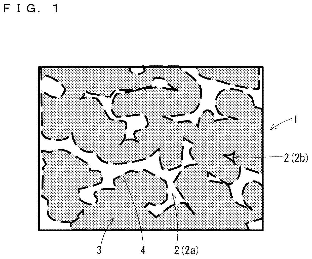
[0030]Next, a lithium composite oxide sintered body plate according to the first embodiment of the present invention will be described. The lithium composite oxide sintered body plate according to the present embodiment is roughly a plate-shaped sintered body in which a plurality of (that is, a large number of) primary particles of a lithium composite oxide having a layered rock-salt structure are bonded. The lithium composite oxide sintered body plate is also a porous body having a large number of pores with a porosity of 15% to 50%. Hereinafter, the lithium composite oxide sintered body plate according to the present embodiment may simply be referred to as a lithium composite oxide sintered body plate.

[0031]Further, the lithium composite oxide sintered body plate is used as a positive electrode or a positive electrode active material layer of a lithium secondary battery (lithium ion secondary battery). Therefore, in the following description, the effect that should be regar...

second embodiment

[0076]In the above-described embodiment, although the addition of one or a plurality of types of elements selected from Nb, Ti, and W is carried out by mixing the oxide powder of the additive element with the raw material powder of the lithium composite oxide, the method of adding additive elements is not limited thereto.

[0077]In the following, a method will be described with which to realize the addition of these additive elements in the additive-added sintered body plate by coating (sol-gel coating) of the additive element-containing phase on the surface of the primary particles using the sol-gel method, which is different from the first embodiment.

[0078]Specifically, a green sheet using the raw material powder is produced by the same procedure as in the first embodiment except that the oxide powder of the additive element is not added, and further, the green sheet is fired.

[0079]Then, the lithium composite oxide sintered body plate without any additive element (hereafter, additiv...

example 1

[0083]LiCoO2 (hereinafter, also referred to as LCO) was selected as the lithium composite oxide, and Nb was selected as the additive element to produce the additive-added sintered body plate according to the first embodiment, and various evaluations were conducted.

[0084]

[0085]First, Co3O4 powder (product of SEIDO CHEMICAL INDUSTRY CO., LTD.) and Li2CO3 powder (product of The Honjo Chemical Corporation) were weighed so as to have Li / Co: 1.02, mixed, and then held at 800° C. for 5 hours.

[0086]Nb2O5 (product of MITSUI MINING & SMELTING CO., LTD.) was added to the obtained mixed powder, and the mixture was pulverized in a pot mill until a particle size distribution where a volume-based D50 was 0.8 μm was obtained. The addition amount was 0.03 wt %. From the atomic weight ratio of the constituent elements of Nb2O5, about 70% of the added Nb2O5 corresponds to the addition amount of Nb as an element. Therefore, the addition amount of Nb is 0.021 wt %. A Microtrack MT3000II (MicrotracBEL Co...


PUM

PropertyMeasurementUnit
inclination angleaaaaaaaaaa
temperatureaaaaaaaaaa

Abstract

A lithium composite oxide sintered body plate includes a porous structure in which a plurality of primary particles of a lithium composite oxide having a layered rock-salt structure are bonded is included, in which a porosity is 15 to 50%, a ratio of the primary particles whose average inclination angle being an average value of angles between a (003) plane of the plurality of primary particles and a plate surface of the sintered body plate is more than 0° and 30° or less is 60% or more, one or more additive elements selected from Nb, Ti, W are contained, and an addition amount of the one or more additive elements to an entire of the sintered body plate is 0.01 wt % or more and 2.0 wt % or less.

Description

TECHNICAL FIELD[0001]The present invention relates to a sintered body plate of a lithium composite oxide, and particularly to a sintered body plate used for a positive electrode of a lithium secondary battery.BACKGROUND ART[0002]A lithium secondary battery (lithium ion secondary battery) in which a sintered body plate of a lithium composite oxide is used for the positive electrode (positive electrode plate) for the purpose of increasing the capacity and increasing the charge / discharge efficiency has already been known (for example, Japanese Patent No. 6374634). The use of such a sintered body plate for the positive electrode is advantageous in that the packing density of the lithium composite oxide as a positive electrode active material is high compared to the case of using a so-called powder dispersion type positive electrode formed by kneading lithium composite oxide powder with an additive such as binder or a conductive agent.[0003]Japanese Patent No. 6374634 discloses a lithium...

Claims


Application Information

Patent Timeline
Patent Type & Authority Applications(United States)
IPC IPC(8): H01M4/1391H01M10/0525C04B38/00
CPCH01M4/1391H01M2004/028C04B38/0058H01M10/0525H01M4/525H01M4/62C04B35/01H01M4/131Y02E60/10C04B38/067C04B2111/00853H01M4/0471H01M2004/021H01M4/366H01M10/4235C04B2235/3203C04B2235/3232C04B2235/3251C04B2235/3258C04B2235/3275C04B2235/6025C04B35/6261C04B2235/6562C04B2235/5445C01G51/42C01P2004/62C04B2235/77C04B2235/5292C04B35/62218C04B2235/787C04B2235/3279C04B2235/3262C04B38/0054C04B38/0061C04B38/0074H01M10/052C04B2235/442C04B2235/96C04B2235/404
Inventor MORISAKI, NOBUHIROYURA, YUKINOBUOHIRA, NAOTONAKASHIMA, EIJIOISHI, KENGO
Owner NGK INSULATORS LTD
Why Eureka
Try Eureka