Mechanically resonant pulse relief valve for assisted clearing of plugged aspiration

a pulse relief valve and mechanical resonance technology, applied in the field of medical devices and intravascular medical procedures, can solve the problems of insufficient or irregular blood flow, embolism of blood clots or thromboses, insufficient blood flow through blood vessels, etc., and achieve the effect of preventing fluid communication

Pending Publication Date: 2021-11-18
STRYKER CORP +1
View PDF0 Cites 5 Cited by
  • Summary
  • Abstract
  • Description
  • Claims
  • Application Information

AI Technical Summary

Benefits of technology

[0019]In this embodiment, the passive pressure oscillation assembly further comprises a spring configured for applying a biasing force to the plunger assembly during operation of the passive pressure oscillation assembly in the normal mode that maintains the first plunger head in a closed position within the plunger cavity, thereby preventing fluid communication between the front plunger cavity region and the center plunger cavity region via the bypass channel, and maintains the second plunger head in a closed position within the plunger cavity, thereby preventing fluid communication between the center plunger cavity region and the aspiration flow path via the outlet channel.

Problems solved by technology

Many vascular system problems stem from insufficient blood flow through blood vessels.
One cause of insufficient or irregular blood flow is a blockage within a blood vessel referred to as a blood clot or thrombus.
Blood clots or thrombi may embolize and form an embolus in a patient vasculature.
At other times, however, such thrombi may lodge in a blood vessel where they can partially or completely occlude the flow of blood.
If the partially or completely occluded vessel feeds blood to sensitive tissue such as, the brain, lungs or heart, for example, serious tissue damage may result.
For example, thrombosis of one of the carotid arteries can lead to stroke, because of insufficient oxygen supply to vital nerve centers in the cranium.
As another example, if one of the coronary arteries is 100% thrombosed, the flow of blood is stopped in that artery, resulting in a shortage of oxygen carrying red blood cells, e.g., to supply the muscle (myocardium) of the heart wall.
Oxygen deficiency reduces or prohibits muscular activity, can cause chest pain (angina pectoris), and can lead to death of myocardium, which permanently disables the heart to some extent.
If the myocardial cell death is extensive, the heart will be unable to pump sufficient blood to supply the body's life sustaining needs.
These drugs, however, do not immediately dissolve the clot from the patient, and are typically ineffective after a predefined window, usually at 2-3 hours after the symptoms arise from the clot.
Mechanical retrieval usually involves a deployable mesh-like grid, such as a stent retriever, and is often complicated and dangerous to perform.
Most aspiration systems are susceptible to tip clogging when the clot that is being aspirated is too large for the aspiration conduit at the distal end of the catheter.
Once tip clogging occurs, the pressure in the system precipitously drops to a level that often results in boiling or cavitation of the aspirate within the system.
As a result, water vapor is introduced into the system, thereby decreasing the efficiency of the aspiration, and in turn, making it more difficult, if not impossible, to ingest the clot into the catheter.
However, these methods either require user intervention to cyclically load the aspiration conduit in response to the realization that the aspiration conduit it has been clogged, which would distract the user from performing the aspiration procedure at hand, or cyclically load the aspiration conduit immediately upon the application of vacuum to the aspiration conduit, and thus, decreases the efficiency of the aspiration procedure during free flow (i.e., when the aspiration conduit is not clogged).

Method used


Image

  • Mechanically resonant pulse relief valve for assisted clearing of plugged aspiration
  • Mechanically resonant pulse relief valve for assisted clearing of plugged aspiration
  • Mechanically resonant pulse relief valve for assisted clearing of plugged aspiration

Examples


Embodiment Construction

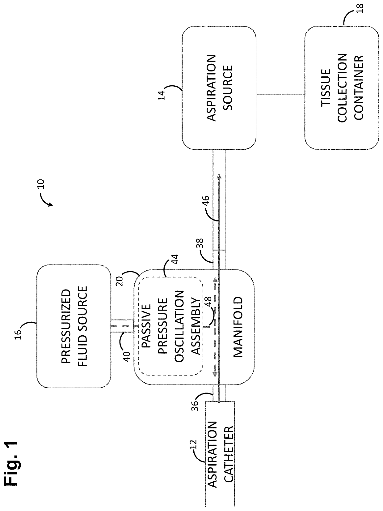
[0073]Referring to FIG. 1, one embodiment of an occlusion aspiration system 10 constructed accordance with the disclosed inventions will now be described. The occlusion aspiration system 10 generally comprises an aspiration catheter 12, an aspiration source 14, a pressurized fluid source 16, a tissue collection container 18, and a manifold 20.

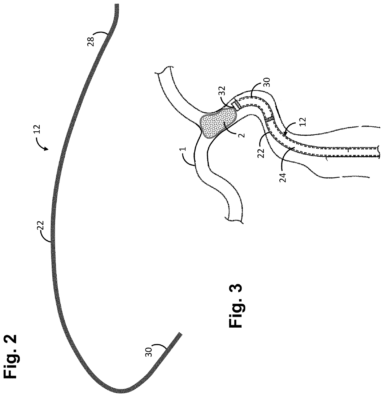
[0074]Referring further to FIGS. 2 and 3, the aspiration catheter 12 comprises an elongated catheter body 22, an aspiration conduit 24 (shown in phantom in FIG. 3) extending through the catheter body 22 between a proximal end 28 and the distal end 30 of the catheter body 22. The proximal end 28 of the aspiration catheter 12 remains outside of a patient 1 and accessible to the operator when the occlusion aspiration system 10 is in use, while the distal end 30 of the catheter body 22 is sized and dimensioned to reach an occlusion 2 (e.g., a clot) with a remote location of the vasculature 1 of the patient, as best shown in FIG. 3. The aspiration c...


PUM


Abstract

An aspiration system comprises an aspiration catheter, an aspiration source fluidly coupled to the aspiration catheter to create an aspiration flow path between the aspiration catheter and the aspiration source, a pressurized fluid source, and a passive pressure oscillation assembly fluidly coupled between the pressurized fluid source and the aspiration flow path. The passive pressure oscillation assembly is configured for being operated between a normal mode that prevents fluid communication between the pressurized fluid source and the aspiration flow path, and an oscillatory mode that pulses fluid communication between the pressurized fluid source and the aspiration flow path. The passive pressure oscillation assembly is configured for being triggered to switch from the normal mode to the oscillatory mode in response to a clog in the aspiration catheter.

Description

RELATED APPLICATION DATA[0001]This patent application is a continuation-in-part of U.S. patent application Ser. No. 17 / 133,684, filed Dec. 24, 2020, which claims priority to U.S. Provisional Application Ser. No. 62 / 965,115, filed Jan. 23, 2020. Each of these patent applications is incorporated by reference in its entirety herein.FIELD OF THE INVENTION[0002]The present disclosure relates generally to medical devices and intravascular medical procedures and, more particularly, to devices and methods for aspirating objects from the anatomy, e.g., a clot from the vasculature of the patient.BACKGROUND OF THE INVENTION[0003]It is often desirable to remove tissue from the body in a minimally invasive manner as possible, so as not to damage other tissues. For example, removal of tissue from within a vasculature, such as blood clots, may improve patient conditions and quality of life.[0004]Many vascular system problems stem from insufficient blood flow through blood vessels. One cause of ins...

Claims


Application Information

Patent Timeline
Patent Type & Authority Applications(United States)
IPC IPC(8): A61B17/22A61M1/00
CPCA61B17/22A61M1/743A61M2025/0019A61B2217/005A61B2017/22079A61M1/74A61M1/75A61B2217/007A61B2090/064
Inventor PORTER, STEPHEN
Owner STRYKER CORP
Why Eureka
Try Eureka