System and method to improve plant growth

a plant growth and plant technology, applied in the field of system and method to improve plant growth, can solve the problems of insufficient accuracy or resolution of targeted or incidental targets, and achieve the effect of improving the economic and resource efficiency of cea operations

Pending Publication Date: 2021-12-16
SPRINGWORKS FARM MAINE INC
View PDF24 Cites 0 Cited by
  • Summary
  • Abstract
  • Description
  • Claims
  • Application Information

AI Technical Summary

Benefits of technology

[0003]The goal of the present invention is to substantially improve the economic and resource efficiency of CEA operations using the microclimate control system and method of the present invention. This is done by redesigning the growing infrastructure to accommodate microclimate monitoring and implementation. The system and method establish, maintain and modify as needed the microclimate adjacent to each plant within a building. The system is an apparatus and associated control functions to create and regulate the climate in the vicinity of each plant. The apparatus includes a substrate for removably retaining plants thereto and one or more components for transferring desired climate elements to each plant retained by the substrate.
[0006]This allows us to shrink the area that needs to be tightly regulated for plant growth proximal to the plants and results in the modified environment contacting the underside of plant leaves. Given that the underside of the plant leaves is where the bulk of gas exchange occurs, this provides an advantage for carbon dioxide enrichment and dehumidification (among other things). The leaves also help provide a boundary layer to trap this modified atmosphere near the stomata of the plant. Ultimately, this should reduce considerably the magnitude of resources spent on atmospheric control for the plants in the building. These advantages can be seen from the following detailed description and the accompanying drawings.

Problems solved by technology

To the extent any underside treatment occurs, it is incidental or not targeted with adequate accuracy or resolution.

Method used


Image

  • System and method to improve plant growth
  • System and method to improve plant growth
  • System and method to improve plant growth

Examples


first embodiment

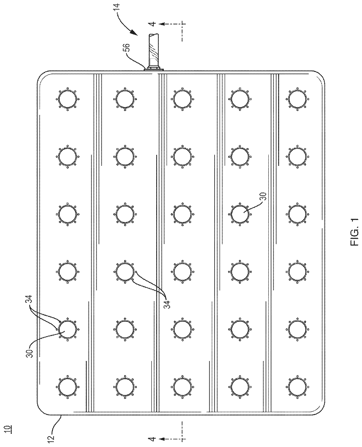
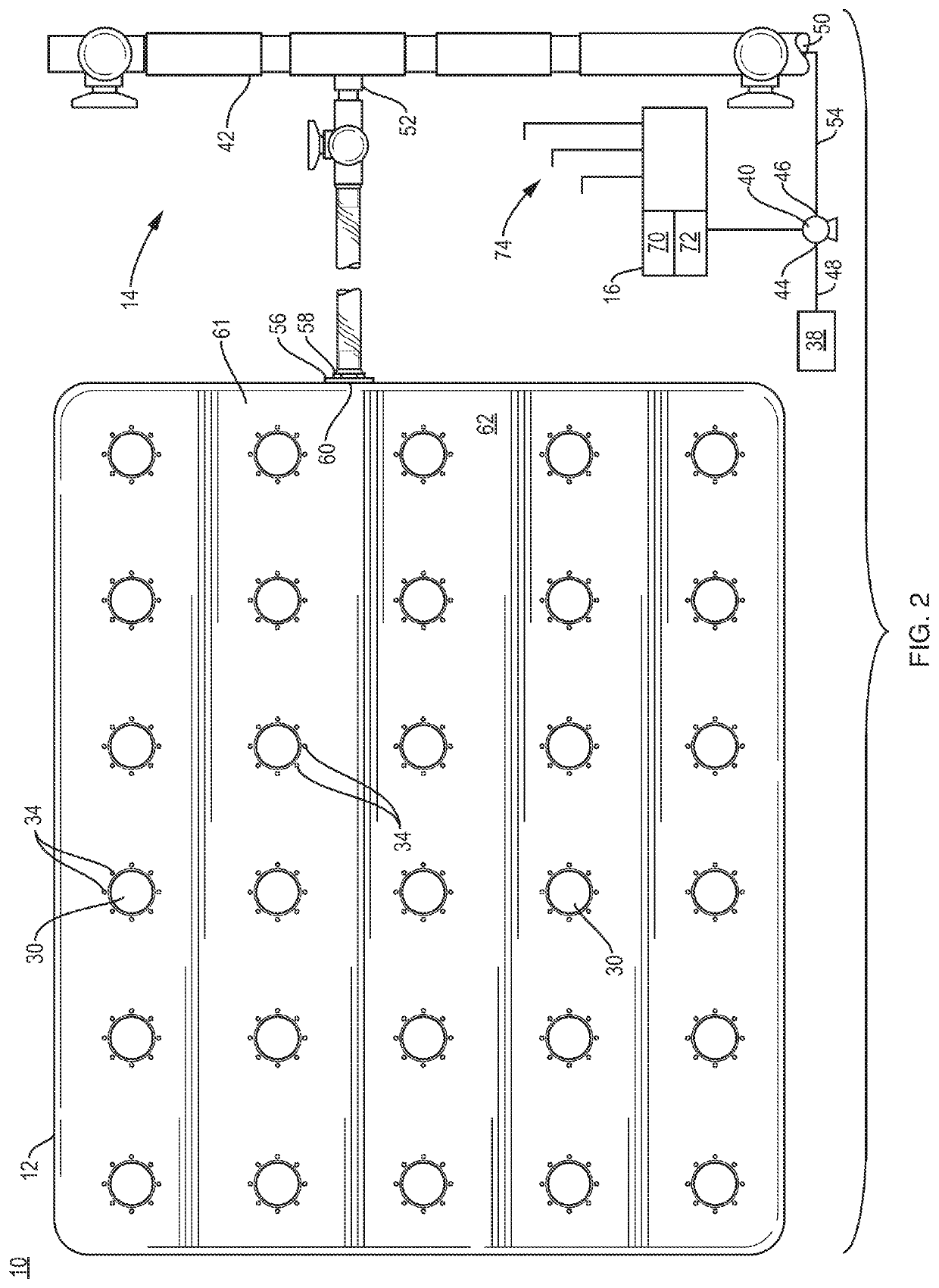
[0019]an efficient plant growth system 10 of the present invention is shown inFIGS. 1, 2 and 4. The system includes a plant retaining substrate 12, a climate delivery subsystem 14 and a microclimate control subsystem 16. The substrate 12, climate delivery subsystem 14 and the microclimate control subsystem 16 are used in combination to deliver a desired atmosphere 18 to underside 20 of a plant 22 that is growing in a building.

[0020]The substrate 12 is fabricated of a material that either floats on or that is retained in position on a surface 24. The surface may be solid or it may be a fluid 26 such as water, for example. The substrate 12 is made of a nonmetallic material such as polyethylene or polypropylene plastic but not limited thereto. The substrate 12 is made with sufficient structural integrity to minimize flexing or other undesirable distortion and to support a plurality if plants retained thereto. The substrate 12 will also maintain a positive buoyancy while on the fluid 26...

second embodiment

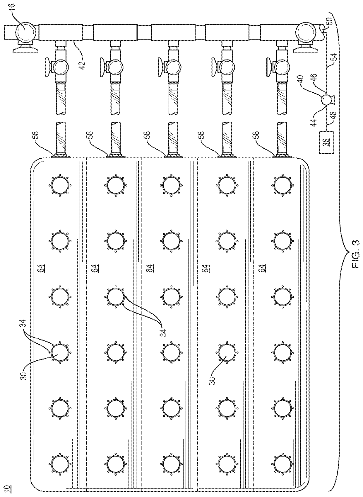
[0027]The climate delivery subsystem 14 further includes one or more gaseous fluid delivery portals 56 of each substrate 12. Each portal 56 includes an input 58 and an output 60. Each input 58 is coupled to one of the plurality of manifold outlets 52, and each output 60 terminates at, within or beyond an interior wall 61 of the substrate 12. Interior 62 of the substrate 12 may be substantially hollow or it may contain a plurality of channels 64 that run at least a portion of a length or width dimension of the substrate 12. When the interior 62 is substantially hollow, represented in FIGS. 1 and 2, only one gaseous fluid delivery portal 56 may be established in the substrate 12 for delivery of the gaseous fluid into the interior 62, although more than one portal 56 may be employed for that delivery. When the interior 62 includes a plurality of channels 64, represented by the invention in FIG. 3, there may be at least one portal 56 for each channel 64, although each channel 64 may hav...

third embodiment

[0030]A variant of the invention relates to aeroponic plant growth. A plant support structure similar to that shown in FIGS. 6 and 7. In an aeroponic process, mist rather than liquid water is delivered into the space 104. That may be done either with piping that delivers the mist at specific locations or by general delivery throughout the space 112. In addition, the top piece 100 and, optionally, the bottom piece 102 may be formed of a porous material rather than a solid material. The plants may be grown directly on and through the porous structure and so plant retainers 110 are not required. In this variant of the present invention for aeroponic operations, the plant support is a porous structure and the portals 114 through which the gaseous fluid is delivered to the underside of the plant may be accomplished through pores adjacent to the plants. As a result, the present invention may be used to establish a microclimate adjacent to a plant grown in an aeroponic process.

[0031]Anothe...


PUM


Abstract

A system and method to facilitate the growth of a plant in a building. The system includes a substrate that is substantially solid, an inflatable raft, or that has an upper member and a lower member with a space therebetween to establish an interior of the substrate. Either form of substrate includes one or more plant retainers and a set of one or more gaseous fluid delivery ports located regularly or irregularly throughout the substrate, including localized in a vicinity of each of the one or more plant retainers. The system further includes a climate delivery subsystem including a gaseous fluid source, a gaseous fluid delivery apparatus, such as a pump and one or more conduits in the substrate, wherein each of the one or more conduits is in communication with each set of the one or more gaseous fluid delivery ports for delivery of the gaseous fluid to an underside of the plant, wherein the one or more conduits are coupled to the gaseous fluid delivery apparatus.

Description

FIELD OF THE INVENTION[0001]The present invention relates to utilizing modified growing infrastructure to economically regulate a plant's microclimate in controlled environment agriculture (CEA).BACKGROUND OF THE INVENTION[0002]CEA is defined by its pursuit of growth optimization through the use of equipment to separate plants from volatile outdoor conditions. Generally, the result has been some form of control system actuating equipment, in a greenhouse or other building, to control the general environmental conditions of the space. Despite the considerable gain in efficiency over conventional field production, this too can be rife with inefficiency. Plants often take up a small percentage of overall volume, but the entire environment is typically conditioned for plant growth. Resources are expended on controlling the humidity, temperature, and carbon dioxide concentration (among other things) of the space as a whole rather than focusing on the microclimate of the plant. This micro...

Claims


Application Information

Patent Timeline
Patent Type & Authority Applications(United States)
IPC IPC(8): A01G25/02A01G7/02A01G13/02
CPCA01G25/023A01G13/0268A01G7/02A01G31/06A01G9/18Y02P60/21A01G9/246Y02A40/25
Inventor KENKEL, TREVOR
Owner SPRINGWORKS FARM MAINE INC
Why Eureka
Try Eureka