An electric arc-blast nozzle made of a material comprising micro-capsules of liquid (CF3)2cfcn and a circuit breaker including such a nozzle

Active Publication Date: 2021-12-23
GENERAL ELECTRIC TECH GMBH
View PDF0 Cites 0 Cited by
  • Summary
  • Abstract
  • Description
  • Claims
  • Application Information

AI Technical Summary

Benefits of technology

The patent is about a new type of circuit breaker that uses a special gas called heptafluoro-iso-butyronitrile to control the electrical arc during a break. The breaker has a nozzle with a special composition made of a fluorocarbon polymer, inorganic filler, and micro-capsules of liquid heptafluoro-iso-butyronitrile. These micro-capsules release the gas as they ablate in the electric arc, which helps to continuously feed the gas into the breaker and improve its performance. The breaker also has a sheath made of a second dielectric material that connects the different parts of the breaker. Using this special composition in the nozzle improves the breaker's electrical endurance, especially when the arc-control gas includes heptafluoro-iso-butyronitrile.

Problems solved by technology

However, SF6 has the major disadvantage of presenting a global warming potential (GWP) of 23 500 (relative to carbon dioxide (CO2) over 100 years) and a time period spent in the atmosphere of 3200 years, which places it among very strong greenhouse gases.
Nevertheless, the regeneration is not at 100% as the gas can include some contaminants such as oxygen or hydrogen from air and / or humidity but also metal vapor from arcing contact and carbon from PTFE nozzle.
Nevertheless, this solution is not widely accepted today in Gas Insulated Switchgear (GIS) as the liquefaction of the gas is not accepted by all customers.
The heptafluoro-iso-butyronitrile will evaporate more in high temperatures and this will increase the density of the gas, making difficult the control of the tightness during the service life of the equipment.
Liquefaction will lower the gas density what could be interpreted as a gas leak by gas densimeter and generate false alarm.

Method used


Image

  • An electric arc-blast nozzle made of a material comprising micro-capsules of liquid (CF3)2cfcn and a circuit breaker including such a nozzle
  • An electric arc-blast nozzle made of a material comprising micro-capsules of liquid (CF3)2cfcn and a circuit breaker including such a nozzle
  • An electric arc-blast nozzle made of a material comprising micro-capsules of liquid (CF3)2cfcn and a circuit breaker including such a nozzle

Examples


Embodiment Construction

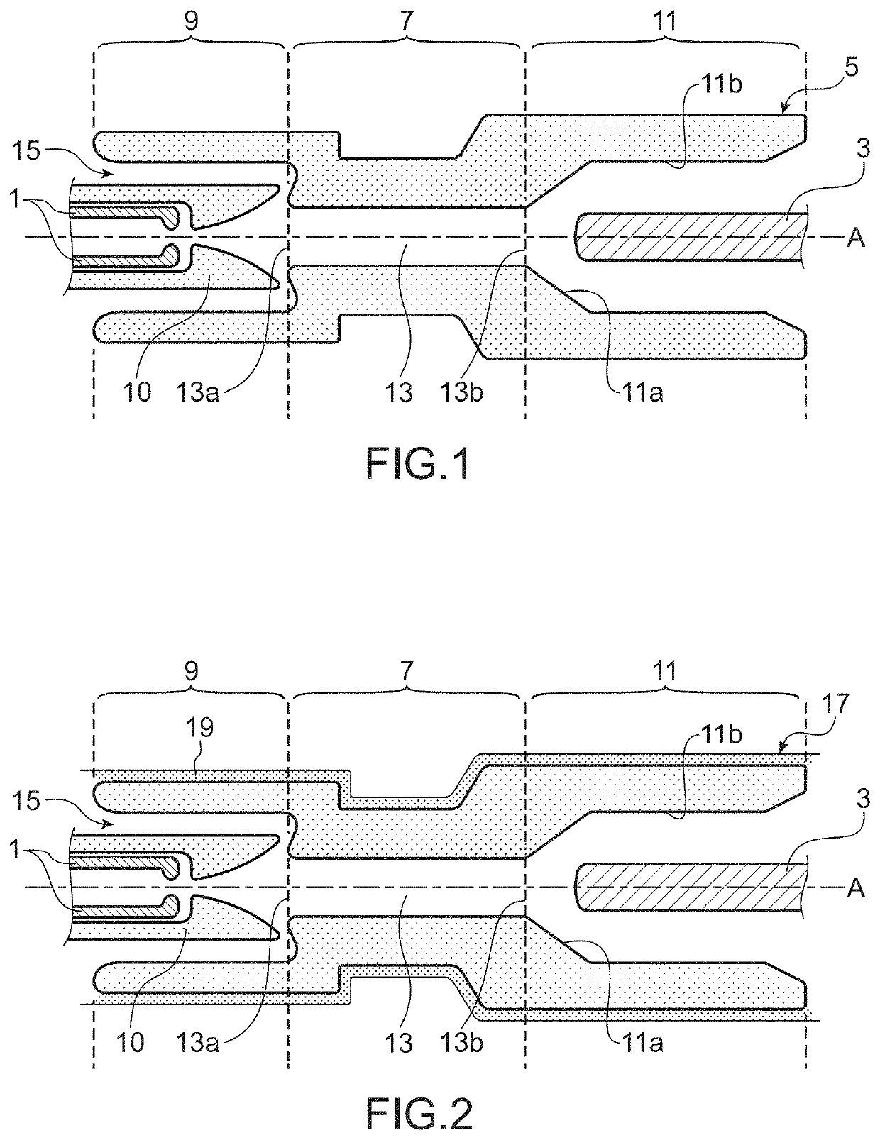
[0084]FIG. 1 shows a circuit breaker portion. The circuit breaker includes:[0085]at least two arcing contacts 1 and 3 that are movable axially relative to each other, along an axis A, between an open position of the circuit breaker in which the arcing contacts 1 and 3 are separated from each other and a closed position of the circuit breaker in which the arcing contacts 1 and 3 are in contact with each other; and[0086]an arc-blast nozzle 5 according to the invention.

[0087]This nozzle 5 includes a throat-forming middle portion 7, an end portion 9 disposed upstream and an end portion 11 disposed downstream, the upstream and downstream disposition of the end portions 9 and 11 being relative to the flow direction of the arc-control gas. These two end portions 9 and 11 extend on either side of the middle portion 7. These portions 7, 9 and 11 are circularly symmetrical about the axis A.

[0088]The middle portion 7 defines internally an axial arc-control passage 13, said axial passage 13 hav...


PUM


Abstract

The invention relates to an electric arc-blast nozzle (5) for a circuit breaker comprising a middle portion (7) forming a throat defining internally an axial passage (13) for interrupting an electric arc, and two end portions (9, 11) extending on either side of the middle portion (7) and being designed to receive respective arcing contacts (1) and (3) that are movable axially relative to each other.The middle portion (7) and the two end portions (9, 11) are made of a same dielectric material obtained from a composition comprising a fluorocarbon polymer matrix, at least one inorganic filler and micro-capsules of liquid heptafluoro-iso-butyronitrile.The invention also relates to a circuit breaker including such a nozzle (5).

Description

TECHNICAL FIELD[0001]The invention relates to the field of electrical insulation and electric arc extinction in high- or medium-voltage equipment.[0002]More particularly, the present invention relates to a nozzle for blowing out an electric arc, this nozzle being designed to be incorporated either in a medium-voltage circuit breaker or in a high-voltage circuit breaker.[0003]Above and below, the expression “medium voltage” is used in the conventionally accepted manner, i.e. the term “medium voltage” refers to a voltage that is greater than 1000 V for AC or greater than 1500 V for DC, but that does not exceed 52,000 V for AC, or 75,000 V for DC.[0004]In addition, the expression “high voltage” is used in the conventionally accepted manner, i.e. the expression “high voltage” refers to a voltage that is strictly greater than 52,000 volts (V) for alternating current (AC) and 75,000 volts for direct current (DC).[0005]The invention also relates to a medium-voltage or a high-voltage circui...

Claims


Application Information

Patent Timeline
IPC IPC(8): H01H33/70
CPCH01H33/7023H01H33/7076H01H33/22H01H33/78H01H2033/566
Inventor KIEFFEL, YANNICKBIQUEZ, FRANÇOIS
Owner GENERAL ELECTRIC TECH GMBH
Why Eureka
Try Eureka