Heat transfer system for a vehicle

a technology of heat transfer system and vehicle, which is applied in the direction of mechanical equipment, machines/engines, transportation and packaging, etc., can solve the problems of reducing affecting the overall performance of the vehicle, and components that do not operate as efficiently, so as to improve reduce the overall performance of the vehicle, and improve the effect of aerodynamic performance and vehicle efficiency

Active Publication Date: 2021-12-30
HONDA MOTOR CO LTD
View PDF115 Cites 4 Cited by
  • Summary
  • Abstract
  • Description
  • Claims
  • Application Information

AI Technical Summary

Benefits of technology

[0003]The disclosure herein provides a heat transfer system for a vehicle, and in a non-limiting example, for an electric vehicle. Electric vehicles utilize systems including batteries, chargers, and other components that do not operate as efficiently if the temperature of the component is not within a specific predetermined range. While a conventional cross airflow heat exchanger is effective for cooling purposes, the flow of ambient air through the heat exchanger creates an aerodynamic drag that can diminish the overall performance of the vehicle. Hence, in order to obtain improved aerodynamic performance and vehicle efficiency, an exemplary embodiment of the disclosure provides a surface heat exchanger, which may be disposed on an underbody or underside of the vehicle.

Problems solved by technology

While effective for cooling purposes, cross airflow through the heat exchanger creates an aerodynamic drag that can diminish the overall performance of the vehicle.
Electric vehicles utilize systems including batteries, chargers, and other components that do not operate as efficiently if the temperature of the component is not within a specific predetermined range.
While a conventional cross airflow heat exchanger is effective for cooling purposes, the flow of ambient air through the heat exchanger creates an aerodynamic drag that can diminish the overall performance of the vehicle.

Method used


Image

  • Heat transfer system for a vehicle
  • Heat transfer system for a vehicle
  • Heat transfer system for a vehicle

Examples


Embodiment Construction

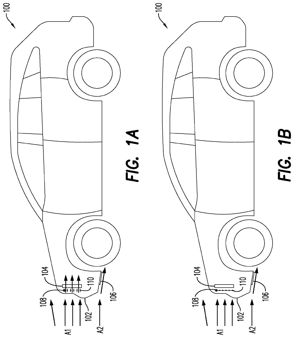
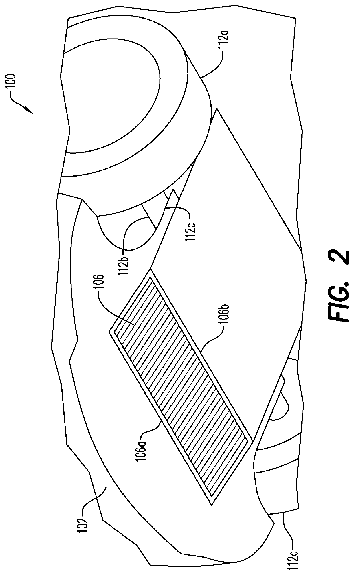
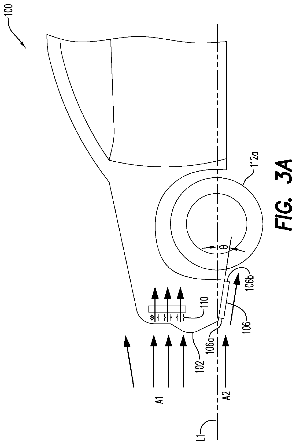
[0028]An exemplary embodiment of the disclosure provides a first heat exchanger and a second, surface heat exchanger, for heat transfer from / to one or more vehicle components. Although the first heat exchanger is also referred to herein as the primary heat exchanger and the second surface heat exchanger is also referred to herein as the secondary heat exchanger, such designations are not limiting as it is to be understood that the second surface heat exchanger may operate as the primary heat exchanger for the vehicle component under certain conditions.

[0029]Under certain predetermined driving conditions, a thermal management control system may close off or obstruct airflow to the primary heat exchanger, and redirect coolant flow to utilize the surface heat exchanger to produce sufficient heat transfer, such as cooling, for the selected vehicle component. As a result, aerodynamic drag may be reduced, vehicle performance may be enhanced, and the driving range for electric vehicles may...


PUM


Abstract

A vehicle heat transfer system includes a flow through heat exchanger, a surface heat exchanger, at least a first vehicle component, and a controller that is operable to selectively transfer heat to or from the first vehicle component with either or both of the flow through heat exchanger and the surface heat exchanger based on one or more operating conditions. In a further aspect, a vehicle heat transfer system includes, a vehicle component positioned on a vehicle that is heated or cooled by a fluid, and a surface heat exchanger positioned on the vehicle, the surface heat exchanger having an inlet that receives the fluid used to heat or cool the vehicle component, an outlet that returns the fluid to heat or cool the vehicle component, and a closed fluid path extending between the inlet and the outlet.

Description

BACKGROUND1. Field of the Disclosure[0001]The present disclosure relates to a heat transfer system for heating or cooling vehicle components, and more particularly, to a heat transfer system including more than one type of heat exchanger.2. Description of Related Art[0002]In a vehicle, such as an electric vehicle, with a conventionally disposed heat exchanger in the front end structure, i.e., under the hood, ambient air generally flows through a front vehicle grille and then through the heat exchanger. The heat exchanger transfers heat from the hot coolant that flows in the heat exchanger tubes to the cooler ambient air blowing through it, thereby providing heat transfer for cooling selected components of the vehicle. While effective for cooling purposes, cross airflow through the heat exchanger creates an aerodynamic drag that can diminish the overall performance of the vehicle. Active grille shutters can be used to regulate the airflow to the heat exchanger to reduce aerodynamic d...

Claims


Application Information

Patent Timeline
Patent Type & Authority Applications(United States)
IPC IPC(8): B60H1/00F01P3/18F01P7/00
CPCB60H1/00278B60H1/00B60H1/00328B60H1/00392B60H2001/0035F01P7/00F01P2003/182B60H2001/003B60H2001/00307F01P3/18B60K11/085B60K11/04F01P7/10Y02T10/88
Inventor MORADNIA, PIROOZFAVELA TENTORI, DANIEL A.HALT, DAVID WAYNEMETKA, MATTHEW L.RAO, PRATAP THAMANNAREYNOLDS, BRIAN R.
Owner HONDA MOTOR CO LTD
Why Eureka
Try Eureka