Internal Structure Observation Device And Internal Structure Analysis System Of Fluid Sample, Internal Structure Observation Method And Internal Structure Analysis Method Of Fluid Sample, And Method For Manufacturing Ceramic

a technology of internal structure analysis and observation device, which is applied in the direction of material analysis, instruments, manufacturing tools, etc., can solve the problems of significant mechanical reliability degradation of ceramics, deformation or cracking of molded bodies, and change of substances,

Pending Publication Date: 2022-02-03
KANAGAWA INST OF IND SCI & TECH +1
View PDF3 Cites 0 Cited by
  • Summary
  • Abstract
  • Description
  • Claims
  • Application Information

AI Technical Summary

Benefits of technology

[0038]In the present invention, it is possible to achieve an in-situ observation of internal structure of the fluid sample, together with an evaluation of a rheology property of the fluid sample containing components different in a refractive index by a rheometer, and a clarification of internal structural change in real time, by using an optical coherence tomography imaging device for generating an optical coherence tomographic image by an internal observation method for observing an internal structure of non-transparent substance by using optical coherence (OCT (Optical Coherence Tomography)).
[0040]It is possible to obtain raw materials of a ceramic optimized by an evaluation of a rheology property of a slurry containing raw materials of the ceramic as the fluid sample, an in-situ simultaneous observation of an internal structure of the fluid sample in an evaluation process, and a clarification of internal structural change. Further, about a molded body of the raw materials of the optimized ceramic, it is possible to optimize a manufacturing of the ceramic based on experimental facts, and not based on experience and intuition, for example, if it is fired while performing an in-situ observation of a sintering process, it is possible to stop firing before generation of inhomogeneous structure and after densification of the ceramic.

Problems solved by technology

Especially, in a dewaxing process and a firing process to be heated at high temperature, a significant change of a substance occurs, such as a melting, an evaporation, a pyrolysis, an oxidation, a sintering contraction, or the like of an added organic substance, and a volume change also occurs, so a deformation or a crack of the molded body may occur.
When these matters exist in a ceramic, it may be a starting point of breakdown, so it will be a cause of strength degradation, and it is known that a mechanical reliability of a ceramic will be deteriorated significantly.
However, even a shear field is applied when measuring a viscosity of the slurry, an aggregation state of particles in the slurry when applying a shear field is not observed, and it cannot be said that correlation between a dispersity and a viscosity is not clarified sufficiently.

Method used


Image

  • Internal Structure Observation Device And Internal Structure Analysis System Of Fluid Sample, Internal Structure Observation Method And Internal Structure Analysis Method Of Fluid Sample, And Method For Manufacturing Ceramic
  • Internal Structure Observation Device And Internal Structure Analysis System Of Fluid Sample, Internal Structure Observation Method And Internal Structure Analysis Method Of Fluid Sample, And Method For Manufacturing Ceramic
  • Internal Structure Observation Device And Internal Structure Analysis System Of Fluid Sample, Internal Structure Observation Method And Internal Structure Analysis Method Of Fluid Sample, And Method For Manufacturing Ceramic

Examples


Embodiment Construction

[0053]Hereinafter, explaining in detail about preferred embodiments of the present invention, with reference to the drawings. In addition, about common components, it is explained by giving common reference number in the drawings. Also, the present invention should not be limited to the following examples, it goes without saying that it can be changed optionally within a scope not deviating from a gist of the present invention.

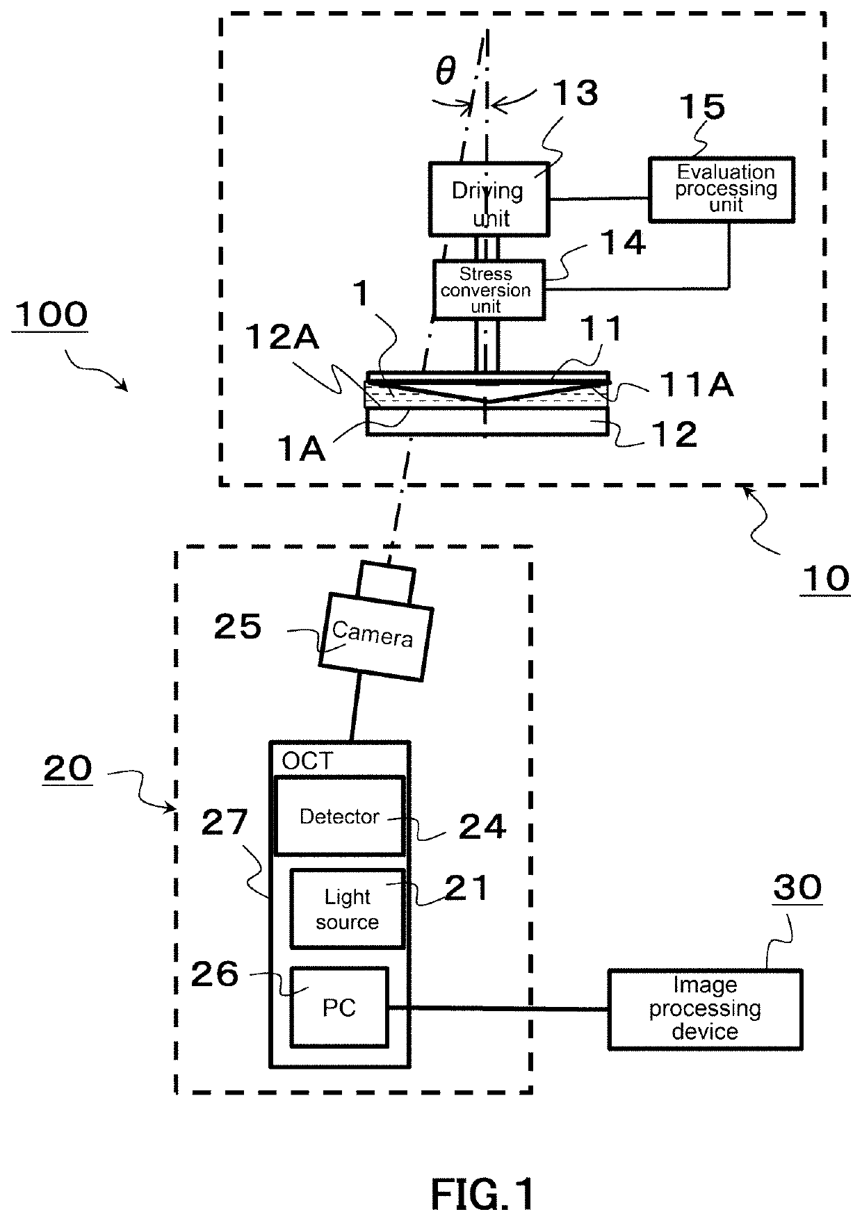
[0054]The present invention is applied to an internal structure analysis system 100 of a slurry, for example in a configuration as illustrated in a block diagram of FIG. 1.

[0055]This internal structure analysis system 100 of a slurry comprises a rheometer 10, an optical coherence tomography imaging device 20, and an image processing device 30.

[0056]The rheometer 10 in this internal structure analysis system 100 is a rotational rheometer for evaluating a rheology property of a fluid sample 1 by an evaluation processing unit 15, by detecting, by a stress convers...


PUM

PropertyMeasurementUnit
pHaaaaaaaaaa
pHaaaaaaaaaa
center wavelengthaaaaaaaaaa

Abstract

The purpose of the present invention is to achieve an in-situ observation of structural change in a shear field of slurry, i.e. an evaluation of a rheology property of slurry containing raw materials of a ceramic as a fluid sample, together with an in-situ observation of internal structure of the fluid sample in an evaluation process, and a clarification of internal structural change. An observation of an internal structure of a fluid sample 1 in an evaluation process of a rheology property by a rheometer 10 is achieved by generating an optical coherence tomographic image by performing an optical coherence tomography by irradiating a light in infrared region from outside of the rheometer 10 to the fluid sample 1, by inclining an optical axis of light in infrared region irradiating the fluid sample 1 for a predetermined angle within an angular range of 1 to 10 degrees with respect to a normal direction of an observation surface 1A of the fluid sample 1 by the optical coherence tomography imaging device 20, together with an evaluation of a rheology property of the fluid sample 1 containing components different in a refractive index by the rheometer 10.

Description

BACKGROUND OF THE INVENTIONField of the Invention[0001]The present invention relates to an internal structure observation device and an internal structure analysis system of a fluid sample containing components different in a refractive index, an internal structure observation method and an internal structure analysis method of a fluid sample, and a method for manufacturing a ceramic. The present application claims priority based on Japanese Patent Application No. 2019-036998 filed in Japan on Feb. 28, 2019, which is incorporated by reference herein.Description of Related Art[0002]Conventionally, a method of using an optical microscope (for example, refer to Non-Patent Literature 1), a method of using an X-ray CT (for example, refer to Non-Patent Literature 2, Non-Patent Literature 3), or the like have been used for an observation of an internal structure of a ceramic.[0003]It is known that a property of a ceramic is controlled by an internal structure of a ceramic. Therefore, it is...

Claims


Application Information

Patent Timeline
Patent Type & Authority Applications(United States)
IPC IPC(8): G01N11/14C04B41/00C04B41/80G01B9/02B28B11/24
CPCG01N11/14C04B41/0072B28B11/243C04B41/80G01B9/02091C04B41/009G01N21/4795G01N21/4133G01N21/84G01N2021/8405G01N11/142G01B11/30G01N19/00G01N21/17G01N21/27
Inventor TAKAHASHI, TAKUMATATAMI, JUNICHITAKABA, HIROKI
Owner KANAGAWA INST OF IND SCI & TECH
Why Eureka
Try Eureka