Electrochromic element, and method for driving the same

a technology of electrochromic elements and methods, applied in static indicating devices, instruments, non-linear optics, etc., can solve the problems of color remaining and spoiling the reliability of ec elements, and achieve the effect of reducing the number of ec elements

Pending Publication Date: 2022-02-03
RICOH KK
View PDF4 Cites 0 Cited by
  • Summary
  • Abstract
  • Description
  • Claims
  • Application Information

AI Technical Summary

Problems solved by technology

One of the problems of the EC elements is color remaining, which is the failure to return to the initial state when the EC elements are driven to return to the initial state after the EC elements in the initial state is driven to change colors.
When the EC elements are used for light control, color remaining spoils reliability of the EC elements.

Method used


Image

  • Electrochromic element, and method for driving the same
  • Electrochromic element, and method for driving the same
  • Electrochromic element, and method for driving the same

Examples


example 1

>

[0210]A solution having the composition described below was prepared in order to form an oxidizable electrochromic layer over a first electrode.

[Composition]

[0211]Oxidizable electrochromic compound: Compound A (50 parts by mass)

[0212]Ion conductive material: PEG400DA (obtained from Nippon Kayaku Co., Ltd.) (50 parts by mass)

[0213]Polymerization initiator: IRGACURE184 (obtained from BASF GmbH) (5 parts by mass)

[0214]Solvent: Methyl ethyl ketone (900 parts by mass)

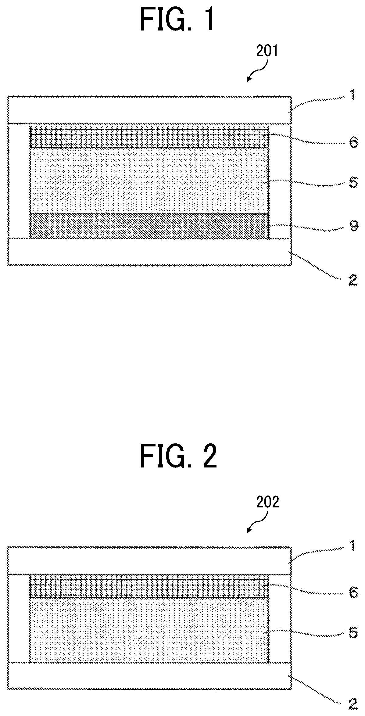
[0215]An ITO glass substrate (40 mm×40 mm, with a thickness of 0.7 mm, and an ITO film thickness of about 100 nm) serving as a first electrode was coated with the obtained solution by a spin coating method. The obtained coating film was irradiated at 10 mW for 60 seconds using a UV irradiator (SPOT CURE, obtained from Ushio Inc.) and annealed at 60 degrees C. for 10 minutes, to form an oxidizable electrochromic layer having an average thickness of 1.3 micrometers.

>

[0216]An ITO glass substrate (40 mm×40 mm, with a thickness ...

examples 2 to 13

[0220]Electrochromic elements of Examples 2 to 13 were produced in the same manner as in Example 1, except that unlike in Example 1, the oxidizable substance in the electrolyte layer was changed to the compounds presented in Table 2 respectively.

example 14

>

[0231]A first electrode was spin-coated with a TFP dispersion liquid of an aqueous polyurethane resin and ATO nanoparticles (obtained from Mitsubishi Materials Corporation), and annealed at 120 degrees C. for 15 minutes, to form an anti-deterioration layer.

>

[0232]An ITO glass substrate (40 mm×40 mm, with a thickness of 0.7 mm, and an ITO film thickness of about 100 nm) serving as a second electrode was coated by a spin coating method with a titanium oxide nanoparticle dispersion liquid (product name: SP210, obtained from Showa Titanium Co., Ltd., with an average particle diameter of about 20 nm). Then, the resultant was annealed at 120 degrees C. for 15 minutes, to form a nanostructure semiconductor material formed of a titanium oxide particle film having a thickness of about 1.0 micrometers.

[0233]Next, the obtained titanium oxide particle film was coated by a spin coating method with a 2,2,3,3-tetrafluoropropanol (hereinafter, abbreviated as “TFP”) solution containing 1% by mass o...


PUM


Abstract

Provided is an electrochromic element including: a first electrode; a second electrode apart from and opposite to the first electrode; an electrolyte layer between the first electrode and the second electrode, containing an oxidizable substance or a reducible substance, or both; and at least one of an oxidizable electrochromic layer between the first electrode and the electrolyte layer, containing an oxidizable electrochromic compound, and a reducible electrochromic layer between the second electrode and the electrolyte layer, containing a reducible electrochromic compound, wherein an oxidation potential of the oxidizable substance is nobler than an oxidation potential of the oxidizable electrochromic compound, a reduction potential of the reducible substance is baser than a reduction potential of the reducible electrochromic compound, an oxidation reaction of the oxidizable substance is irreversible, and a reduction reaction of the reducible substance is irreversible.

Description

CROSS-REFERENCE TO RELATED APPLICATIONS[0001]This patent application is based on and claims priority pursuant to 35 U.S.C. § 119(a) to Japanese Patent Application Nos. 2020-131051 and 2021-100010, filed on Jul. 31, 2020 and Jun. 16, 2021, respectively, in the Japan Patent Office, the entire disclosure of which is hereby incorporated by reference herein.BACKGROUNDTechnical Field[0002]The present disclosure relates to an electrochromic element, and a method for driving the same.Description of the Related Art[0003]Electrochromism is a phenomenon that in response to application of a voltage, a substance undergoes an oxidation-reduction reaction reversibly and changes colors. Electrochromism is the subject of extensive research and development because electrochromism can be utilized for, for example, light control and signage.[0004]Electrochromic elements (hereinafter, “electrochromic” may be described as “EC”) utilizing electrochromism typically include an ionic conductive electrolyte l...

Claims


Application Information

Patent Timeline
Patent Type & Authority Applications(United States)
IPC IPC(8): G02F1/155G02F1/1523G09G3/19G02F1/1503
CPCG02F1/155G02F1/1503G09G3/19G02F1/1525G02F2001/164G02F1/15G02F1/1516G02F1/15165G02F1/163G02F2001/1502
Inventor URA, NAOKIKANEKO, FUMINARI
Owner RICOH KK
Why Eureka
Try Eureka