Holding Magnets and Magnet System for Implantable Systems Optimized for MRI

a technology applied in the field of holding magnets and magnet systems for implantable systems optimized for mri, can solve the problems of not being strong enough to hold the external transmitter device in the proper position, damage to adjacent tissue in the patient, and magnetic resonance imaging, etc., to achieve favorable magnetic flux, reduce the mass of the implant magnet, and improve the effect of magnetization

Pending Publication Date: 2022-03-10
MED EL ELEKTROMEDIZINISCHE GERAETE GMBH
View PDF1 Cites 0 Cited by
  • Summary
  • Abstract
  • Description
  • Claims
  • Application Information

AI Technical Summary

Benefits of technology

[0020](ii) more than 50%, or preferably more than 55% of the mass of the implant magnet is located on a side of the middle plane at which the outermost surface is located, wherein the edges of the implant magnet at the inner end surface are chamfered. Criterion (i) defines the distribution of the magnetic flux generated by the implant magnet itself, i.e. when placed in isolation in air or vacuum. According to this criterion, the larger part of the magnetic flux is on one side of the middle plane, and this side is the side on which in the “assembled state”, i.e. when the implant magnet is arranged in the implant device, the outermost surface of the implant device would be located. In other words, the implant magnet is devised so that by itself it already generates the bigger part of its flux in the region where it is needed for establishing an attractive holding force with an external device, i.e. more to the outside than to the inside of the body. The second criterion (ii) specifies that more than half of the mass of the implant magnet is located on the side of the middle plane at which the outermost surface located. This again helps with generating the magnetic flux closer to the outside region than the inside region with respect to the implant magnet. One way of reducing the mass of the implant magnet towards the inside of the middle plane is by providing for chamfered edges at the inner end surface of the implant magnet. This shape also allows for a more favorable magnetic flux.
[0021]In some embodiments, the north and south end portions of the external magnet are formed from anisotropic magnet elements each having a preferred magnetization direction, wherein the anisotropic magnet elements are joined with each other or with an intermediate portion arranged in between, wherein the preferred magnetization directions are arranged at an angle with respect to the overall dipole moment of the external magnet as a whole. The anisotropic magnet elements can e.g. be made by applying an external magnetic field while the magnet is formed, which may for example involve sintering. The anisotropic magnets have the advantage that they allow for higher magnetizations in their final state. The anisotropic magnets will not have their final magnetic strength after manufacture yet, but will only acquire it after a final magnetization using a strong magnetic pulse. While an isotropic magnet can be magnetized by a strong magnetic pulse in any direction, the anisotropic magnets can only be magnetized in their preferred magnetization directions established upon manufacture. This is actually an advantage in the manufacturing process of the magnet as a whole, because the magnet can be assembled from anisotropic magnet elements with the preferred magnetization directions in the north and south end portions inclined with respect to the overall magnetization direction, but before the anisotropic magnet elements are fully magnetized. This makes the handling of the anisotropic magnet elements prior to the assembly, as well as the joining of the magnet elements much easier. It is then possible to fully magnetize the anisotropic magnet elements in the joint state by applying an external magnetic pulse aligned with the direction of the eventual overall magnetic dipole moment. During this magnetization process, the magnetization directions of the anisotropic magnet elements as part of the entire implant magnet will be preserved, while their strength will be increased.
[0022]In some embodiments, the implant magnet may have on at least part of the inner end surface (913) a layer of magnetic soft material, such as for example soft iron, applied. This may help to shield a magnetic field generated by the implant magnet itself toward the inside of the body and thereby may reduce artefacts during MRI-scanning. The implant magnet may be a rare earth magnet, e.g., a rare earth magnet including neodymium, samarium, terbium, dysprosium and / or holmium.

Problems solved by technology

One problem arises when the patient undergoes Magnetic Resonance Imaging (MRI) examination.
Among other things, this may damage the adjacent tissue in the patient.
In addition, the external magnetic field B from the MRI may reduce or remove the magnetization m of the implant magnet 202 so that it may no longer be strong enough to hold the external transmitter device in proper position.
The implant magnet 202 also may cause imaging artifacts in the MRI image, there may be induced voltages in the receiving coil, and hearing artifacts due to the interaction of the external magnetic field B of the MRI with the implanted device.
Torque and forces acting on the implant magnet and demagnetization of the implant magnet are especially an issue with MRI field strengths at 1.5 Tesla and higher.
Thus, for many existing implant systems with magnet arrangements, it is common to either not permit MRI, or limit use of MRI to lower field strengths.

Method used


Image

  • Holding Magnets and Magnet System for Implantable Systems Optimized for MRI
  • Holding Magnets and Magnet System for Implantable Systems Optimized for MRI
  • Holding Magnets and Magnet System for Implantable Systems Optimized for MRI

Examples


second embodiment

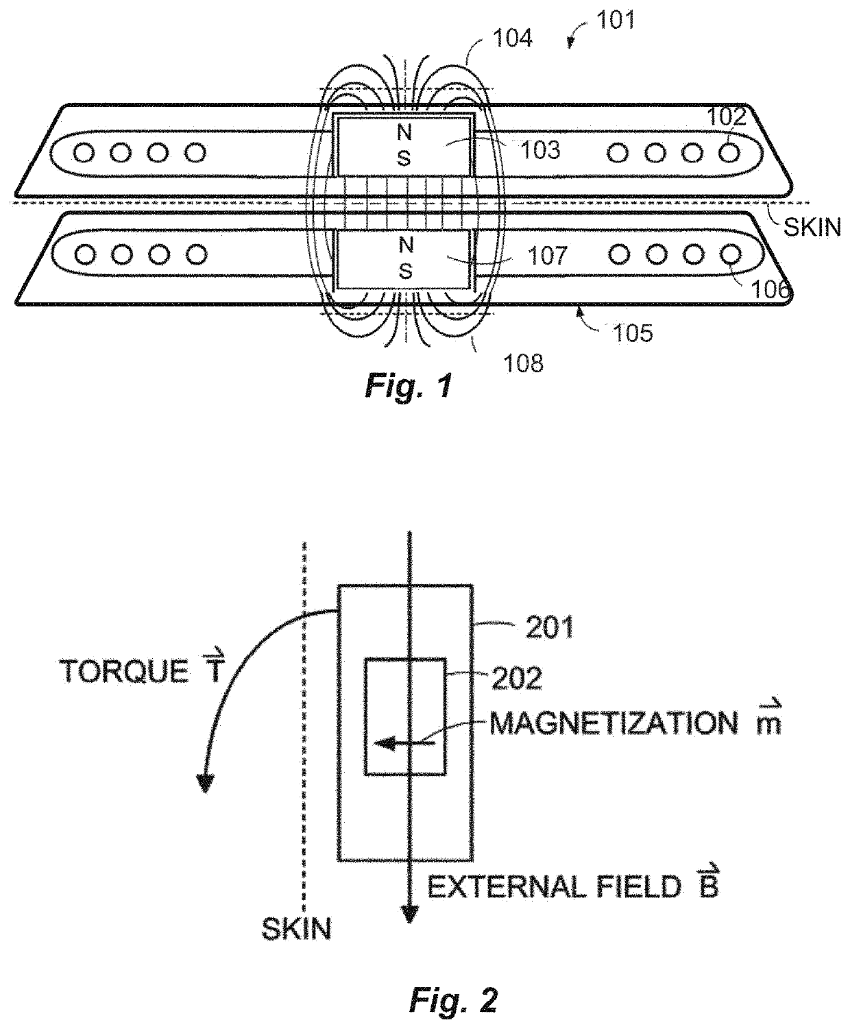
[0011]According to the invention, the implant magnet “as a whole” has an “overall magnetic dipole moment” which is at least approximately parallel to the outermost surface, or in other words, approximately parallel to the skin in the implanted state. As the skilled person will appreciate, the magnetic dipole moment m of a magnetic body as a whole is a macroscopic quantity defining the “strength” of the magnetic dipole. When arranged in an external magnetic field having a flux density B, a torque τ is generated that corresponds to the vector product of the magnetic dipole moment m and the flux density B, i.e. τ=m×B. Accordingly, the overall magnetic dipole moment m of the implant magnet can be readily determined when placed in an external magnetic field: the implant magnet will orient itself to bring the dipole moment m in alignment with the flux density B of the external magnetic field, thereby revealing the direction of the magnetic dipole moment m, while its magnitude is defined b...

first embodiment

[0077]FIG. 14 again schematically shows an implant device 905 in a sectional view including an implant magnet 900, as well as an external device 955 comprising an external magnet 950. By magnetic interaction between the internal and external magnets 905, 950, the external device 955 may be attached to the skin 401 of a patient. The internal magnet 900 is comprised of two halves, one being formed by the north end portion 914 and the other by the south end portion 915. The hatched lines with arrowheads indicate the local magnetization M. It is seen that the local magnetizations in the north and south end portions 914, 915 have deviating directions, thereby leading to what was referred to as the “magnetic angle” with reference to the invention above. Each of the north and south end portions 914, 915 has an individual magnetic dipole moment 916, 917, which corresponds to the space integral over the magnetization M in the respective portion. It is then seen that although the overall dipo...


PUM


Abstract

Embodiments of the present invention are directed to an implantable hearing implant, such as cochlear implants. The implantable hearing implant includes an implant device containing signal processing circuitry configured to receive an implant communications signal transmitted from an external transmitting coil. The implantable hearing implant further includes an implant magnet configured to cooperate with a corresponding external holding magnet in an external device located over the overlying skin to magnetically hold the external device against the overlying skin. The implant magnet has a north magnetic pole, a south magnetic pole, and as a whole has an overall magnetic dipole moment that is parallel to or at an angle of 300 or less with respect to the outermost surface. The implant magnet has a north end portion and a south end portion, each having an individual magnetic dipole moment that is inclined with respect to the overall magnetic dipole moment.

Description

CROSS-REFERENCE TO RELATED APPLICATIONS[0001]This application claims priority from U.S. Provisional Patent Application 63 / 075,912 filed on Sep. 9, 2020, which is incorporated herein by reference in its entirety.FIELD OF THE INVENTION[0002]The present invention relates to at least partially implantable devices such as partly implantable hearing devices, for example cochlear implants, and specifically, to implantable magnets for interaction with external magnets in such devices.BACKGROUND ART[0003]Some hearing implants such as Middle Ear Implants (MEI's) and Cochlear Implants (CI's) employ cooperating attachment magnets located in the implant and the external part to magnetically hold the external part in place over the implant. For example, as shown in FIG. 1, a typical cochlear implant system may include an external transmitter device 101 containing transmitting coil 102 and an external attachment magnet 103. The external attachment magnet 103 has a conventional cylindrical disc-sha...

Claims


Application Information

Patent Timeline
Patent Type & Authority Applications(United States)
IPC IPC(8): A61N1/08A61N1/36A61N1/372
CPCA61N1/086A61N1/37223A61N1/36038A61N1/37229
Inventor ZIMMERLING, MARTIN
Owner MED EL ELEKTROMEDIZINISCHE GERAETE GMBH
Why Eureka
Try Eureka