
Eureka
For R&D, Eureka makes reading and utilizing patents & technical documents easy.
Eureka AIR
Designed for self-driven R&D workflows. Generate viable solutions, solve complex R&D challenges, empower your innovation with AI.

Eureka Materials
Designed for material experts only. Revolutionize your material R&D, from search, analyze, to developing new materials.

TechResearch
Generate reliable direction feasibility study reports for your R&D in just a few steps.

TechSeek
Discover and master advanced knowledge NOW. Basics, ideas, possibilities, all at once.

TechMind
As an expert in R&D Theories, TechMind can generates customized viable solutions instantly.

TechRisk
Analyze your overall solution with one click, know your potential R&D risks in advance.

TechMonitor
Get weekly tech updates, stay abreast of the latest tech innovations and key insights.
Compact smart electric motor
- Summary
- Abstract
- Description
- Claims
- Application Information
AI Technical Summary
Benefits of technology
Problems solved by technology
Method used
Image

Examples
first embodiment
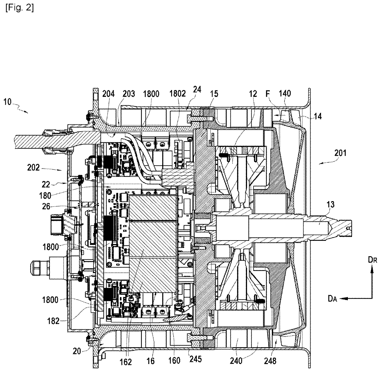
[0047]A section view of a smart motor 10 is shown schematically in FIG. 2, according to the invention.
[0048]The smart motor 10 illustrated in FIG. 2 comprises an electrical machine 12 acting as an electromechanical converter and endowed with a rotating portion defining an axial direction DA and a radial direction DR. FIG. 2 is a section view in a plane comprising the axial direction DA and the radial direction DR.
[0049]The smart motor 10 further comprises an impeller 14, electrical filtering means 16, an electronic control unit 18, and a housing 20 or casing, inside which are accommodated the electrical machine 12, the electronic control unit 18 and the filtering means 16.
[0050]The impeller 14 is mechanically coupled to the electrical machine 12 by a transmission shaft 13, which allows the electrical machine to drive the impeller 14.
[0051]The housing 20 has a hollow cylindrical shape with, in the embodiment illustrated in FIG. 2, a circular cross section. The axis of revolution of t...
second embodiment
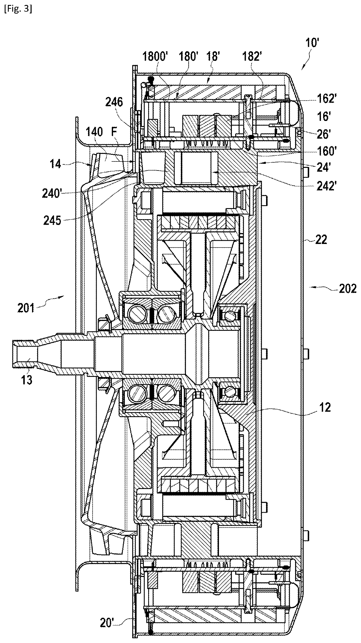
[0071]A section view of a smart motor 10′ according to the invention is illustrated schematically in FIG. 3.
[0072]Elements identical to the first embodiment illustrated in FIG. 2 bear the same numerical references.
[0073]FIG. 3 is a section view in a plane comprising the axial direction DA and the radial direction DR.
[0074]In this second embodiment, the impeller 14 is coupled mechanically to the electrical machine 12 via the transmission shaft 13 and the housing 20′ has a hollow cylindrical shape with a circular cross section, the cylindrical shape being less long in the axial direction DA and larger in the radial direction DR than in the first embodiment illustrated in FIG. 2. The axis of revolution of the housing 20′ is congruent with the axis of rotation DA of the electrical machine 12, which is congruent with the axis of rotation of the transmission shaft 13 and of the impeller 14.
[0075]The electrical machine 12, the electrical filtering means 16′ and an electronic control unit 1...
PUM
 Abstract
Description
Claims
Application Information
 - R&D Engineer
- R&D Manager
- IP Professional
- Industry Leading Data Capabilities
- Powerful AI technology
- Patent DNA Extraction
Browse by: Latest US Patents, China's latest patents, Technical Efficacy Thesaurus, Application Domain, Technology Topic, Popular Technical Reports.
© 2024 PatSnap. All rights reserved.Legal|Privacy policy|Modern Slavery Act Transparency Statement|Sitemap|About US| Contact US: help@patsnap.com