
System and method for manufacturing pipes

Pending Publication Date: 2022-03-24
TRANSCANADA PIPELINES
View PDF0 Cites 0 Cited by
  • Summary
  • Abstract
  • Description
  • Claims
  • Application Information

AI Technical Summary

Benefits of technology

The patent text describes an improved way of joint preparation and welding using a narrow bevel design and a metal cored arc welding process or flux cored arc welding process. This approach reduces or eliminates the need for a backing and can potentially lower repair rates relative to conventional approaches. The size and shape of the welding groove affects the quality of the weld and the cost and time required to form the weld. Smaller welding grooves result in better quality welds, faster weld completion, and reduced material consumption. However, wider welds may have lower quality and be more prone to failure. The technical effects of this patent text are improved joint preparation and welding using a narrow bevel design and a metal cored arc welding process or flux cored arc welding process.

Problems solved by technology

Meeting stringent weld quality requirements may be difficult and costly.
Attaching a backing requires approaching the welding groove from a radially inner end of the pipe, which may (in various cases) be costly, difficult and time-consuming.
Furthermore, the backing does not normally form part of the weld or joint and thus needs to be removed after welding, thereby increasing time and labor requirements.
The addition of backing to the welding process can considerably increase time and cost of the weld.
Welding consumables such as flux generally reduce productivity but are nonetheless required to protect the weld.
This is particularly true for oil and gas transmission pipelines that pass through High Consequence Areas (HCAs) since weld failure may cause leakage of toxic or flammable materials.
The design parameter space for welding joints may be large.
The size and shape of the welding groove influences the quality of the welding joint and affects the cost and time required to form the weld.
Larger welding grooves require more material and a longer time for weld completion.
Higher heat input applied on larger welding grooves reduces the quality of the welding joint and may negatively affect the material properties, e.g. it may lead to softening in the heat-affected zone (HAZ) of the base material.
Larger welding grooves may also lead to multiple welding beads arranged side-by-side (i.e. axially) in the same layer (i.e. same general radial location), potentially reducing the quality of the weld and introducing additional joining edges (defining inter-bead connections) which may be more prone to failure.
Alternatively, wide weaving welding may be used but this may expose the base material to higher temperatures for longer to the detriment of the base material.
Additionally, wider welds may also be more difficult to clean and grind, e.g. chipping slag after welding, especially regions between adjacent weld beads in the same layer.
Furthermore, excessively large welds may not be amenable to fast and / or automatic non-destructive evaluation (NDE) of welds, e.g. ultrasonic or radiographic testing.
Wide angle welding grooves (˜60°) are susceptible to shearing under tensile loading of the pipe.
Zero gap welding grooves may require a backing (welded backing, fastened, internally clamped, or tack welded), which is undesirable as outlined above, e.g. the welding groove then would normally need to be worked from both radial ends of the pipe wall, thereby increasing costs.
Additionally, compared to larger welding grooves, smaller welding grooves may not be always be readily workable, e.g. the electrode or other welding parts may be hindered by inner or side walls of the welding groove.
In some cases, welds formed in small welding grooves may lead to defects on the side walls of the welding groove and increased porosity and / or slag inclusions.

Method used


Image

  • System and method for manufacturing pipes
  • System and method for manufacturing pipes
  • System and method for manufacturing pipes

Examples


Embodiment Construction

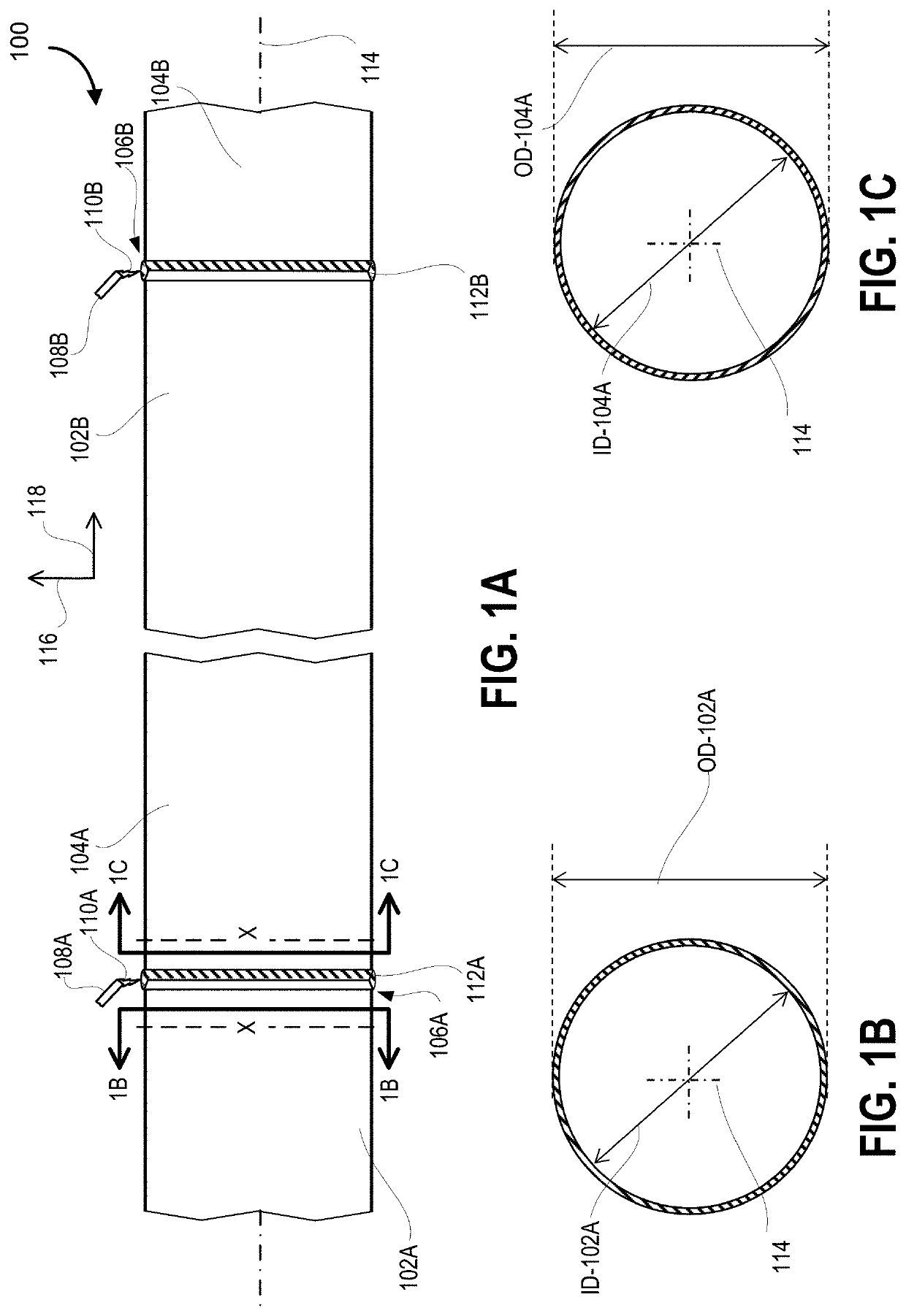
[0046]Pipelines are manufactured using one or more tubular sections butt welded together at axial ends. The butt weld includes a welding groove whose shape and geometry needs to be specified as part of a welding protocol. The welding groove typically extends around the pipe circumferentially. Pipes, methods of manufacturing them, and joints to be used therein are described below. The joints can be used for a pipeline, which can be a pipe assembly, and the pipeline can convey various objects, such as gas (e.g., natural gas or natural gas liquids), oil, water, biofuels, sewage, slurry, or fluids (e.g., sewage, steam), among others.

[0047]Pipes can be above ground, buried, under the sea, and may be subject to various stresses, such as high pressure, heat, corrosive conditions, adverse environmental conditions (e.g. heat, cold, humidity, wind, impacts), etc. The examples are not limited to pipes per se, and some embodiments may be related to any welding of joints.

[0048]An improved weldin...


PUM

PropertyMeasurementUnit
Lengthaaaaaaaaaa
Lengthaaaaaaaaaa
Lengthaaaaaaaaaa

Abstract

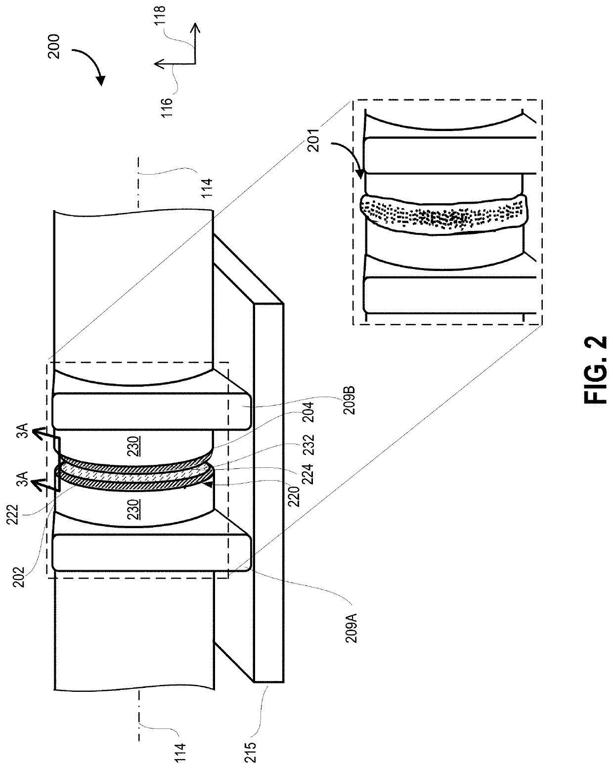
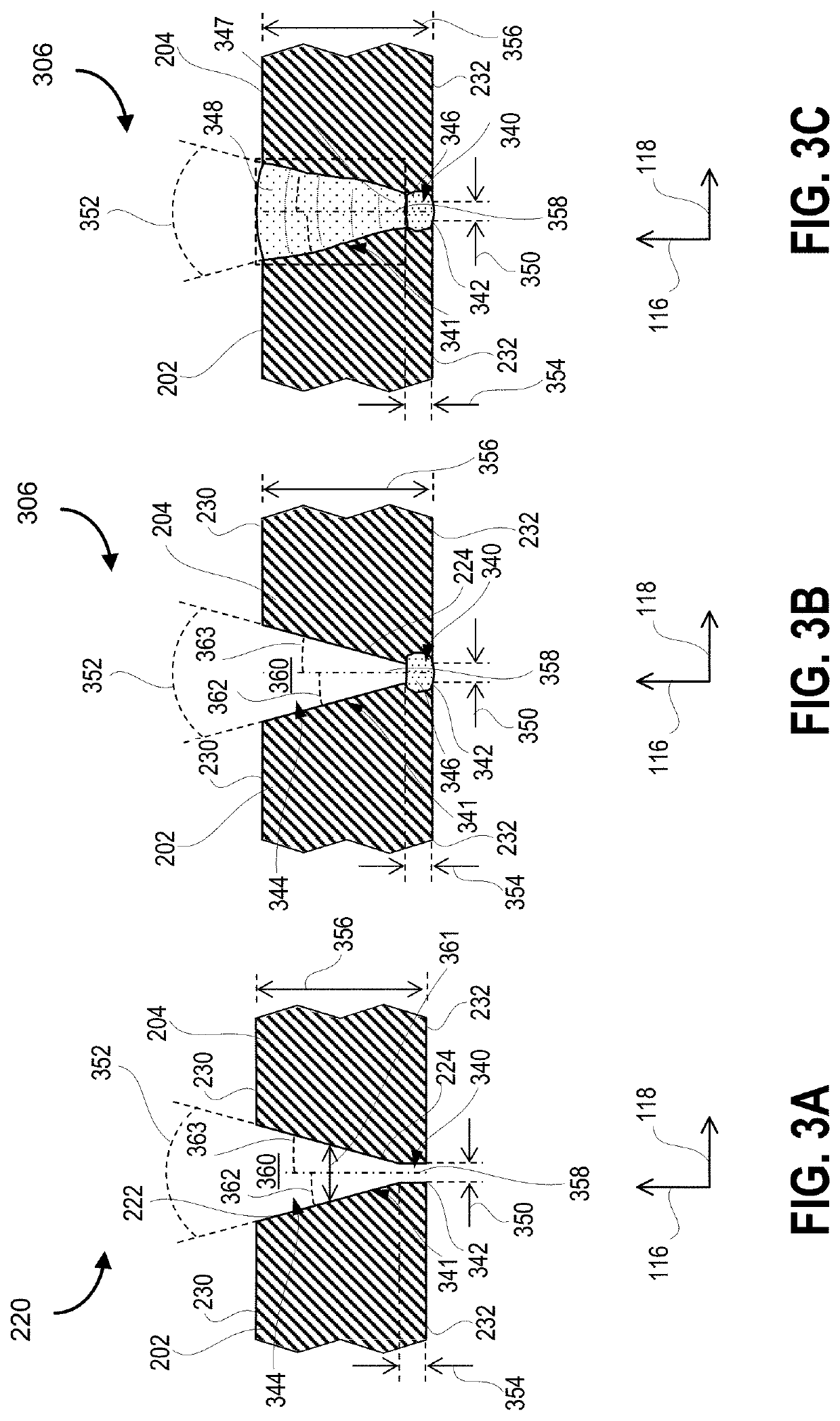
An improved approach for welding a pipe, the pipe comprising first and second tubular sections welded to each other along a welding groove having an open-ended profile which is circumferentially extended around a pipe axis. The welding groove is formed between first and second axial edges and includes a root formed at a radially inner end of the welding groove and a portion of the welding groove radially outward relative to a root. The root axially spaces the first tubular section apart from the second tubular section substantially between 1 mm and 6 mm and the first and second axial edges are angled substantially between 6-20° (or 6-30°) away from each other radially outwardly to form the portion. The root can receive a first welding bead to fill the root and create a joint between the first and second tubular sections and additional welding beads may be utilized.

Description

CROSS REFERENCE[0001]This application is a non-provisional of, and claims all benefit to, including priority from, U.S. Application No. 63 / 081,039, entitled: SYSTEM AND METHOD FOR MANUFACTURING PIPES, filed Sep. 21, 2020, incorporated herein by reference in its entirety.FIELD[0002]This application relates to manufacturing pipes, and in particular, to welding joints used in oil and gas transmission pipelines, joining two tubular sections together using a specific welding sequence and / or joint preparation.INTRODUCTION[0003]In manufacturing pipes and pipelines, e.g. for the oil & gas industry, separate tubular sections, such as pipes, components (e.g. elbows, tees, flange valves), and / or adapters, are joined together by butt welding complementary axial ends of the tubular sections.[0004]Butt welding in pipes involves forming a welding groove between two tubular sections that are to be joined. The welding groove may take on a variety of shapes, e.g. V-shape, single-bevel, U-shaped, comp...

Claims


Application Information

Patent Timeline
IPC IPC(8): F16L13/02
CPCF16L13/02B23K9/0282B23K9/0286B23K9/173B23K2103/04B23K9/16B23K9/14B23K9/0216
Inventor ZHOU, YAOKONG
Owner TRANSCANADA PIPELINES
Learn More