
Battery thermal management device and method for improving safety and performance of battery

a battery thermal management and battery technology, applied in battery, cell components, electrochemical generators, etc., can solve the problems of increasing fires, not easy to cope, and lithium-ion batteries are vulnerable to fire, so as to reduce the required amount of insulating coolant, prevent fire, and raise the level of insulating coolan

Inactive Publication Date: 2022-04-21
STANDARD TESTING & ENG INC
View PDF0 Cites 5 Cited by
  • Summary
  • Abstract
  • Description
  • Claims
  • Application Information

AI Technical Summary

Benefits of technology

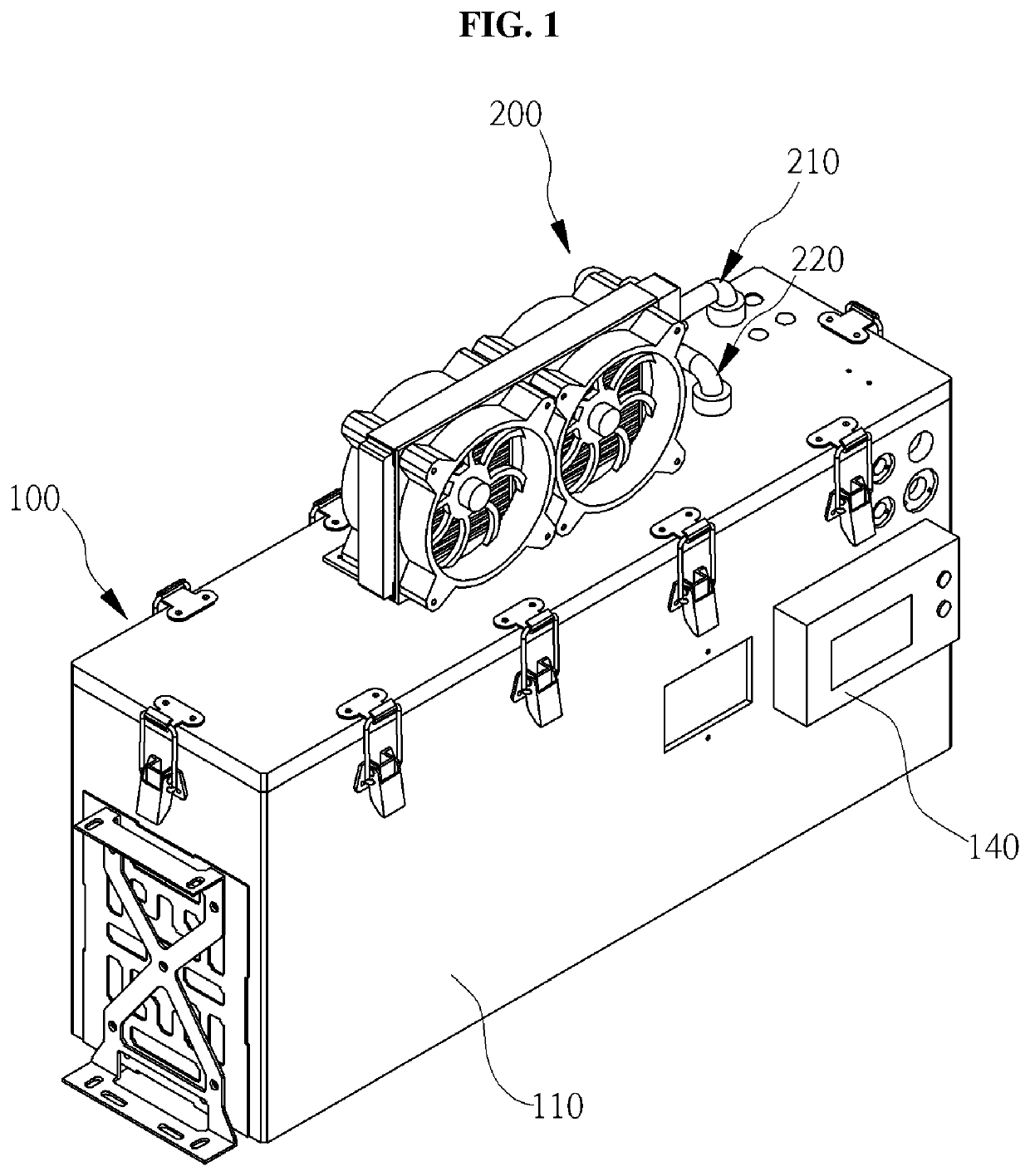
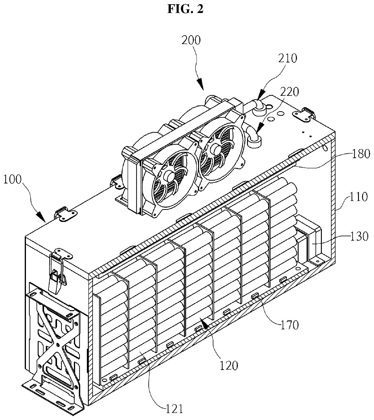
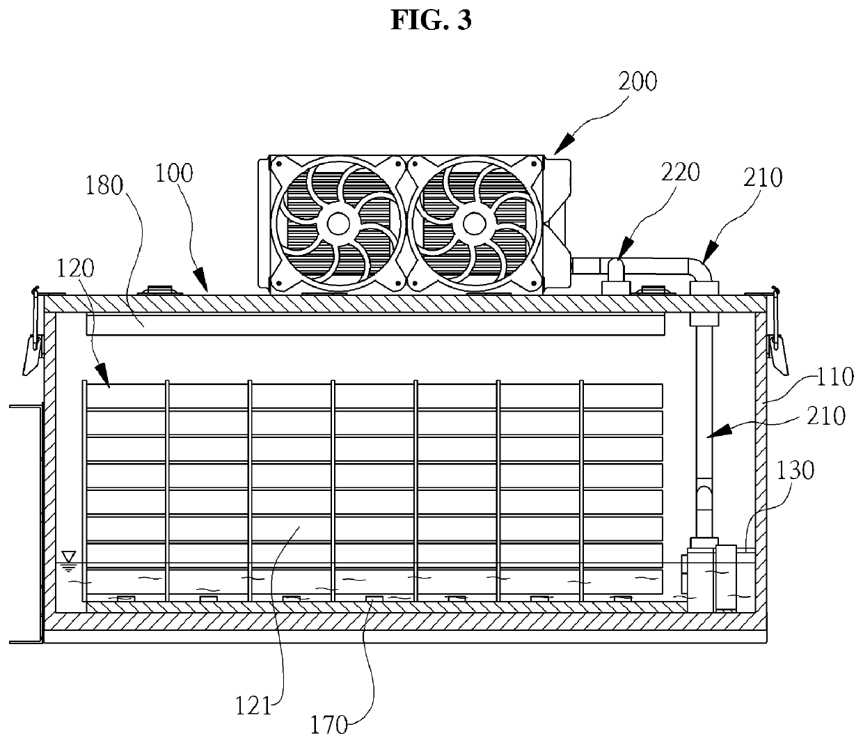
The present invention is a battery thermal management device and method that can adjust the level of insulating coolant for efficient management. It reduces the amount of insulating coolant needed by providing an effective suction head relative to the storage capacity. This results in improved performance of the battery.

Problems solved by technology

Among various kinds of power storage units, lithium-ion batteries are vulnerable to fire that occurs due to high temperature and heat.
If efficient cooling of batteries is not performed, more fires would be reported.
Therefore, there is a problem in that it is not easy to cope with ESS fires due to complex characteristics, and moreover, there is a more serious problem that lithium-ion batteries exhibit unique characteristics such as thermal runaway and re-ignition.
Polyolefin-based polymers such as polyethylene or polypropylene, which are materials commonly used for separators, have a melting point in a range of 125 to 160° C. and have poor stability at high temperatures.
When the pressure rises to exceed a certain level due to gas expansion, flammable gas and electrolyte leak out of the battery cell and ignite.
Causes of thermal runaway include perforation of a separator caused by a mechanical impact, electrical factors such as overcharging or overdischarging, and defects in the product itself.
In some cases, it is also possible that batteries are burned due to external fires that are not related to the batteries.
In the case of a fire that occurs in a battery composed of a large number of battery cells, even though the fire of a battery cell that is first ignited is extinguished, another battery cell that is adjacent to the firstly ignited battery is thermally shocked by thermal conduction or radiant heat, resulting in thermal runaway thereof due to their own electrical energy.
This results in fire starting again.
Due to the thermal runaway and re-ignition of the lithium-ion battery, it is almost impossible to extinguish the fire if the initial suppression of a battery fire fails.
In a fire site, there is a risk of an electric shock and explosive combustion due to the generation of metallic substances and combustible gases in the battery.
It also causes fatal damage to peripheral devices.
However, the extinguishing function of the insulating coolant is very limited because only a small amount of insulating coolant can be contained in a battery casing.
In addition, the extinguishing performance of the insulating coolant is poor.
Therefore, when a big fire occurs, it is impossible to extinguish the fire with the insulating coolant.
However, the use of a large amount of an expensive insulating coolant results in an increase in manufacturing cost and in a considerable increase in weight.
However, in this case, although the amount of the insulating coolant decreases due to losses attributable to evaporation and leakage of the insulating coolant, it is difficult to replenish the insulating coolant.
In addition, when a fire occurs even though cooling is performed, there is a problem in that the fire cannot be extinguished with only the insulating coolant.

Method used


Image

  • Battery thermal management device and method for improving safety and performance of battery
  • Battery thermal management device and method for improving safety and performance of battery
  • Battery thermal management device and method for improving safety and performance of battery

Examples


Embodiment Construction

[0052]The above objectives, features, and advantages of the present invention will become more apparent from the following detailed description taken in conjunction with the accompanying drawings. With reference to the following detailed description and the accompanying drawings, the ordinarily skilled in the art may easily embody the technical concept of the invention. Further, in describing the exemplary embodiments of the present invention, well-known functions or constructions will not be described in detail since they may obscure the gist of the present invention. Hereinafter, preferred embodiments of the present invention will be described in detail with reference to the accompanying drawings.

[0053]It will be further understood that the terms “comprises” and / or “comprising”, or “includes” and / or “including”, or “has” and / or “having”, when used in this specification, specify the presence of stated features, regions, integers, steps, operations, elements, and / or components, but ...


PUM

PropertyMeasurementUnit
melting pointaaaaaaaaaa
temperatureaaaaaaaaaa
flow rateaaaaaaaaaa

Abstract

The present invention relates to a thermal management system and a thermal management method for cooling a heat-generating electronic device such as a battery and for extinguishing a fire occurring in the heat-generating electronic device. More particularly, the present invention relates to a thermal management system and a thermal management method that are capable of cooling a heat-generating electronic device such as a battery of an energy storage system (ESS) in various ways at multiple stages and of extinguishing a fire in the heat-generating electronic device. The present invention has an effect of preventing fire by cooling a heating-generating element such as a battery of an energy storage device. In addition, the present invention has an effect of stopping a cooling operation and starting a fire extinguishing operation when a fire occurs during the cooling operation.

Description

CROSS REFERENCE TO RELATED APPLICATION[0001]A claim for priority under 35 U.S.C. § 119 is made to Korean Patent Application No. 10-2020-0135555 filed on Oct. 19, 2020 in the Korean Intellectual Property Office, the entire contents of which are hereby incorporated by reference.BACKGROUND OF THE INVENTION1. Field of the Invention[0002]The present invention relates to a thermal management system and a thermal management method for cooling a heat-generating electronic device such as a battery and for distinguishing a fire occurring in the heat-generating electronic device. More particularly, the present invention relates to a thermal management system and a thermal management method that are capable of cooling a heat-generating electronic device such as a battery of an energy storage system (ESS) in various ways at multiple stages and of distinguishing a fire in the heat-generating electronic device.2. Description of the Related Art[0003]Recently, the use of energy storage systems (ESS)...

Claims


Application Information

Patent Timeline
Patent Type & Authority Applications(United States)
IPC IPC(8): H01M10/613H01M10/6569H01M10/6568H01M10/6556H01M10/48H01M2/10A62C5/02A62D1/02
CPCH01M10/613H01M10/6569H01M10/6568H01M10/6556H01M2200/00H01M2/1016A62C5/02A62D1/0071H01M10/486A62C3/16A62C35/023A62C37/38Y02E60/10H01M50/213H01M10/643H01M50/271H01M50/262H01M10/633H01M10/63H01M10/6567H01M10/627H01M10/653H01M2200/10H01M50/20
Inventor LEE, SEUNGHYUNSHIN, WOOJUNGPARK, HANSOLPARK, JUNHYUN
Owner STANDARD TESTING & ENG INC
Features
  • Generate Ideas
  • Intellectual Property
  • Life Sciences
  • Materials
  • Tech Scout
  • Unparalleled Data Quality
  • Higher Quality Content
  • 60% Fewer Hallucinations
Learn More