

Electromechanical brake pressure generator for a hydraulic brake system of a vehicle
- Summary
- Abstract
- Description
- Claims
- Application Information
AI Technical Summary
Benefits of technology
Problems solved by technology
Method used
Image

Examples
Embodiment Construction
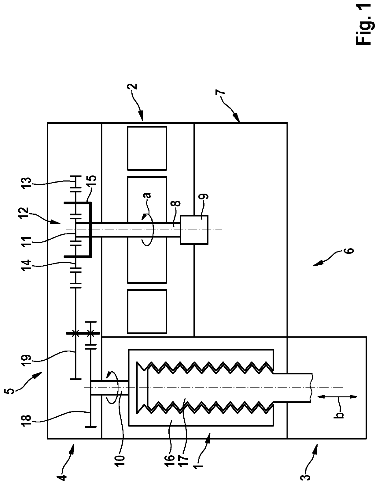
[0022]In accordance with FIG. 1, the electromechanical brake pressure generator for a hydraulic braking system (not depicted here in further detail) of a vehicle encompasses a spindle drive unit 1 by which a rotational motion a, generated on the input drive side by an electric drive motor 2, is converted into a translational motion b for piston actuation of a hydraulic piston / cylinder unit 3.
[0023]Located in the power flow between electric drive motor 2 and spindle drive unit 1 is a multi-stage gear linkage 4 that provides conversion of a rapid motor rotation speed of electric drive motor 2 down to a rotation speed that is slower in comparison, for driving spindle drive unit 1. Gear linkage 4 is disposed on a first end face 5, serving as a mechanical connection side, of drive motor 2 and spindle drive unit 1.
[0024]Second end face 6 located oppositely from first end face 5 serves, conversely, as an electrical connection side. Disposed on this second end face 6 is an electronic contro...
PUM
 Abstract
Description
Claims
Application Information