Electrical current feed-through

a current feed-through and electric current technology, applied in the field of current feed-through, can solve the problems of damage to the insulation of the electrical feed-through, high thermal load in the outer region of the current feed-through, etc., and achieve the effect of reducing heat conduction, reducing specific resistance, and not compromising electrical conductivity on the whol

Pending Publication Date: 2022-05-05
VITESCO TECH GERMANY GMBH
View PDF5 Cites 2 Cited by
  • Summary
  • Abstract
  • Description
  • Claims
  • Application Information

AI Technical Summary

Benefits of technology

[0021]Here, a material which for example has a lower specific resistance may be selected in some portions. Due to the low diameter, the heat conduction is reduced, wherein, on account of the adjustment of the specific resistance, the electrical conductivity on the whole is not compromised.
[0022]It is also expedient if the device is formed by an extended electrically conductive element....

Problems solved by technology

A disadvantage of the current feed-throughs known in the prior art is in particular that, due to the integrally bonded connection between the current-conducting pin and the components in the interior of the catalytic converter that are to be electrically contacted, a high thermal load occurs in the ...

Method used


Image

  • Electrical current feed-through
  • Electrical current feed-through

Examples


Embodiment Construction

[0029]The following description of the preferred embodiment(s) is merely exemplary in nature and is in no way intended to limit the invention, its application, or uses.

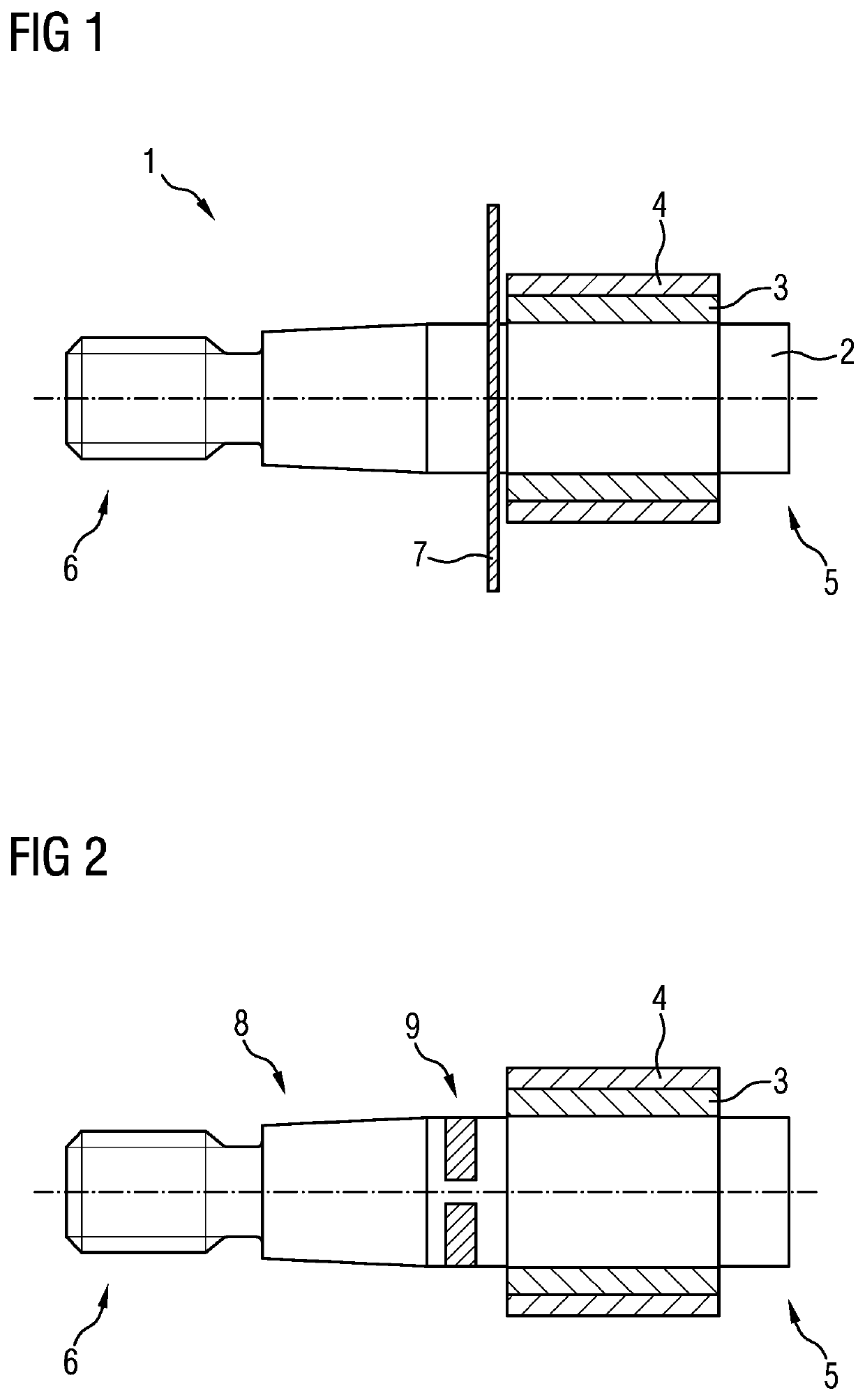
[0030]FIG. 1 shows a current feed-through 1. This is formed from an electrically conductive pin 2, which is surrounded at least in some portions by an electrically non-conductive insulation layer 3. In the region of the insulation layer 3 there is additionally arranged a metallic sleeve 4, in which the electrically conductive pin 2 and the insulation layer 3 are received.

[0031]The right-hand end 5 of the pin 2 forms what is known as the hot end, which protrudes into the catalytic converter (not shown) and is in electrically conductive contact with the electrical conductor in the catalytic converter. The left end 6 forms what is known as the cold end, which forms the contact region outside the catalytic converter.

[0032]Furthermore, the heat shield 7 is seen, which is arranged on the side of the metal sleeve 4 and the i...


PUM


Abstract

A current feed-through for an electrically heatable catalytic converter, wherein the catalytic converter has in the interior thereof at least one electrical conductor, which is electrically contactable by the current feed-through, having a central electrically conductive element, which is guided from the interior of the catalytic converter through the outer housing wall thereof, having an electrical insulation layer, which surrounds the electrically conductive element on its radial outer face, and having a metallic sleeve, in which the electrically conductive element and the electrical insulation layer is received, wherein at the current feed-through or directly adjacently to the current feed-through there is arranged a device for reducing the heat conduction from the interior of the catalytic converter along the current feed-through to a contact face arranged outside the catalytic converter.

Description

CROSS-REFERENCE TO RELATED APPLICATIONS[0001]This application claims priority to PCT Application PCT / EP2020 / 067597, filed Jun. 24, 2020, which claims priority to German Patent Application No. DE 10 2019 210 368.5, filed Jul. 12, 2019. The disclosures of the above applications are incorporated herein by reference.FIELD OF THE INVENTION[0002]The invention relates to a current feed-through for an electrically heatable catalytic converter, wherein the catalytic converter has in the interior thereof at least one electrical conductor, which is electrically contactable by the current feed-through, having a central electrically conductive element, which is guided from the interior of the catalytic converter through the outer housing wall thereof, having an electrical insulation layer, which surrounds the electrically conductive element on its radial outer face, and having a metallic sleeve, in which the electrically conductive element and the electrical insulation layer is received.BACKGROU...

Claims


Application Information

Patent Timeline
IPC IPC(8): F01N3/20F01N3/28
CPCF01N3/2026F01N3/28F01N2510/02F01N2260/02F01N2260/20F01N2240/16F01N3/2013F01N2260/08Y02T10/12
Inventor BRÜCK, ROLFLANGENFELD, PHILIPPBRUGGER, MARCKONIECZNY, KATRINPACE, LORENZOAHLERS, STEFAN
Owner VITESCO TECH GERMANY GMBH
Why Eureka
Try Eureka