Gear box arrangement

a gear box and gear box technology, applied in the direction of marine propulsion, vessel parts, vessel construction, etc., can solve the problems of human error in the control of the craft, inherent stability loss, and the cost of lower drag foil, so as to achieve low consumption propulsion, reduce the effect of vessel wash, and high efficiency

Pending Publication Date: 2022-05-12
ARTEMIS TECH LTD
View PDF0 Cites 0 Cited by
  • Summary
  • Abstract
  • Description
  • Claims
  • Application Information

AI Technical Summary

Benefits of technology

[0040]Vessel wash significantly reduced.
[0041]Thus, the hydrofoil system of the present invention provides a high efficiency and low consumption propulsion system for high speed marine travel whilst providing autonomous control of a fully submerged actively controlled foiling waterborne vessel.

Problems solved by technology

However, all control is manual e.g. using a control system with a mechanical lever arm, and the flaps require human intervention, which inherently requires extensive experience by a user and exposes the craft control to human error.
In the same way as for aircraft, there is an inherent trade-off between a requirement for faster and more accurate control and overall drag (a lower drag foil will come at the cost of inherent stability).

Method used


Image

  • Gear box arrangement
  • Gear box arrangement
  • Gear box arrangement

Examples


first embodiment

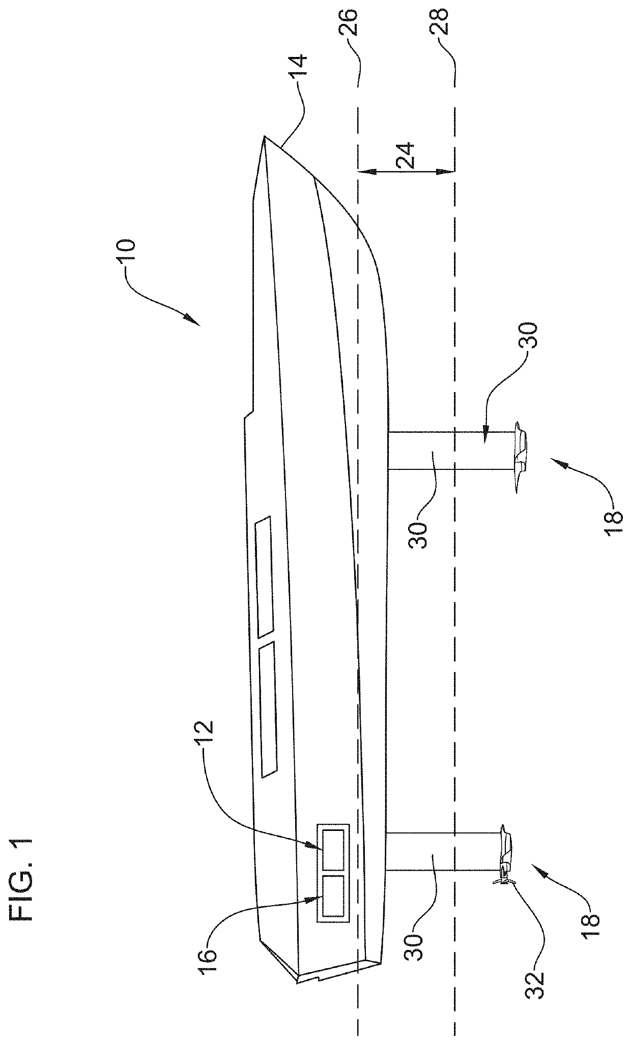
[0053]FIG. 1 shows a waterborne vessel in the form of a monohulled vessel 10 provided with an embodiment of a hydrofoil system in accordance with the present invention. The hydrofoil system comprises a controller 12 located within the hull 14 of vessel 10.

[0054]A battery system 16 is located adjacent controller 10, and in electrical communication with controller 10. In the embodiment of FIG. 1, battery system 16 comprises a Power Electronics Control Unit (PECU).

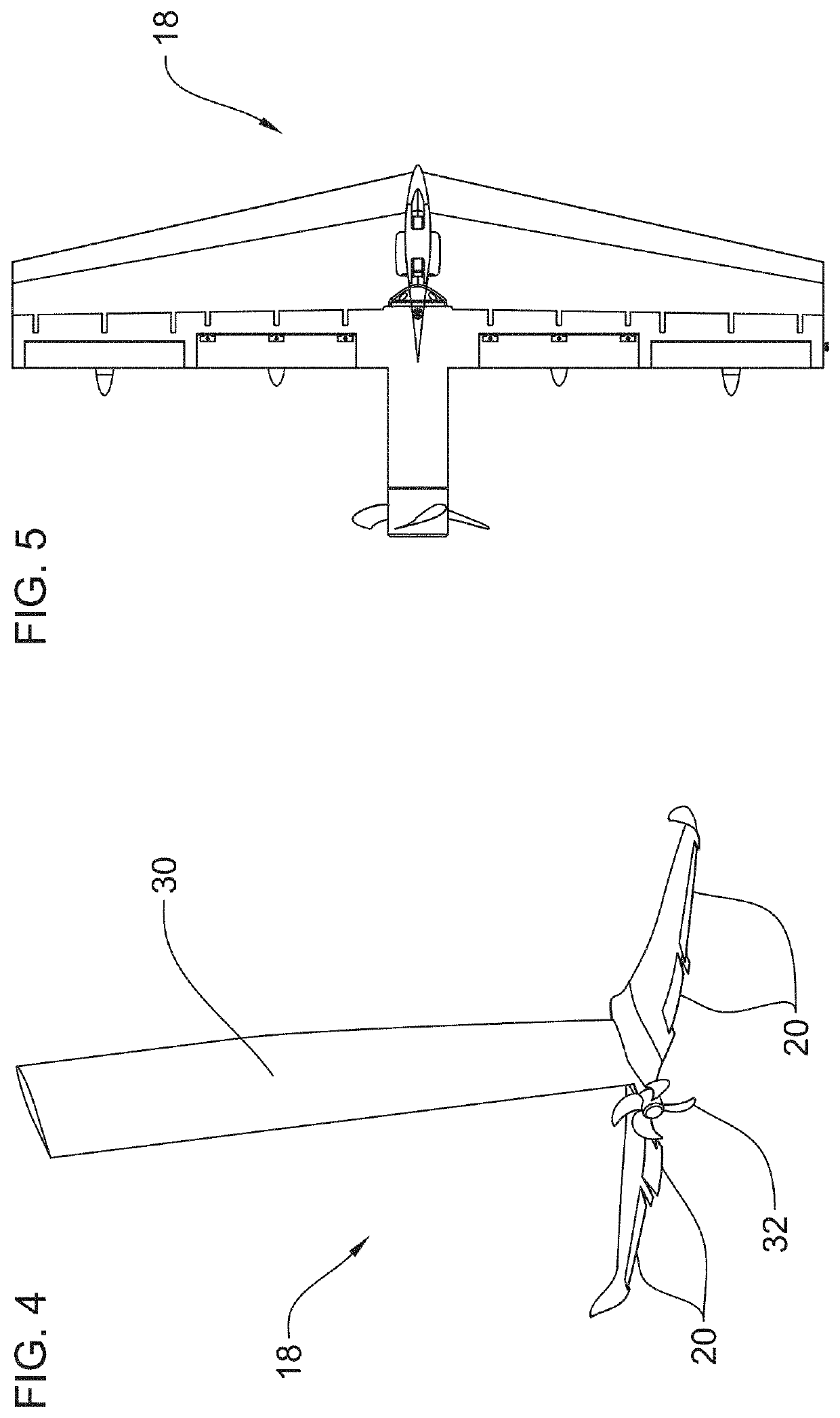
[0055]A foil 18 is located on the outer surface of the foil hull below the floating waterline. Foil 18 comprises a plurality of adjustment members 19 operable to vary the lift characteristics of the vessel 10 during travel. Each adjustment member comprises a flap 20 and associated actuator 22. Actuators 22 can be either electric or hydraulic and may be integrated within foil 18 (as shown in FIG. 1) or may be located within the vessel 10 itself depending on the vessel size and associated foil size. Actuators 22 operate to cont...

second embodiment

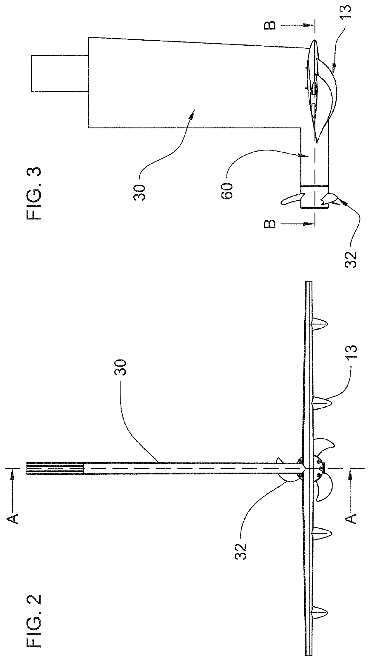
[0066]In a second embodiment, shown in FIG. 8, foil 18 comprises a housing 60 defining a receiving space in which engine 42 and gearbox 44 are received. Housing 60 provides a watertight housing for engine 44. Engine 42 and gearbox 44 are located adjacent one another within housing 60 housing 60 and are connected via shaft 66 that transmits the torque and rotation from engine 42 to the gearbox 44. The outer surfaces of both engine 42 and gearbox 44 are located adjacent the interior surface of housing 60 such that heat generated during use is absorbed from engine 42 and gearbox 44 by housing 60 and subsequently dissipated into the surrounding water, thus providing an efficient cooling system that avoids the need for mechanical or forced flow of fluid past the engine 42 and / or gearbox 44 within housing 60.

[0067]Propeller 32 is connected to gearbox 44 distal to engine 42 and is engaged with gearbox 44 via propeller shaft 33. Propeller 32 connects to propeller shaft 33 by means of a coni...


PUM


Abstract

The present invention relates to a gearbox system for mounting on a waterborne vessel with a hydrofoil, the gearbox system comprising:
a housing having an interior surface defining an interior space of defined dimension;
a gearing system comprising a propeller shaft engagement portion, the gearing system located within the interior of the housing; and
an engine located within the interior space of the housing and in mechanical communication with the gear box;
wherein the housing is water-tight and wherein the gearing system and engine are in thermal contact with the interior surface of the housing.
Further provided is a hydrofoil system including such a gearbox system and a waterborne vessel including such a hydrofoil system.

Description

CROSS REFERENCE TO RELATED APPLICATION(S)[0001]This patent application claims priority from, and incorporates by reference the entire disclosure of, Application No. GB 2017848.9 filed on Nov. 12, 2020.FIELD OF THE INVENTION[0002]The present invention relates to a gearbox arrangement for use with hydrofoil systems employed on yachts, sailboats, ships, and other waterborne vessels. In particular, the present invention relates to such a gearbox with heat transfer cooling system.BACKGROUND OF THE INVENTION[0003]A sailing hydrofoil is a wing-like structure mounted under the hull of a boat, such as a yacht, that provides a speed advantage over more traditional boat designs. The sailing hydrofoil works with its wing-like appendage. Just like a wing on an aircraft provides lift, a hydrofoil in the water accomplishes the same thing. The main difference is that a hydrofoil does not need to be as large as an airplane wing, because the water is much denser than air. As the boat increases its sp...

Claims


Application Information

Patent Timeline
Patent Type & Authority Applications(United States)
IPC IPC(8): B63B1/24B63B1/28
CPCB63B1/246B63B1/26B63B1/286B63H21/17B63H23/02B63H2021/216B63H2023/0283Y02T70/50
Inventor PERCY, IAININGOUF, ROMAIN
Owner ARTEMIS TECH LTD
Why Eureka
Try Eureka