
Smart manufacturing framework

Pending Publication Date: 2022-05-19
ODICO AS
View PDF0 Cites 0 Cited by
  • Summary
  • Abstract
  • Description
  • Claims
  • Application Information

AI Technical Summary

Benefits of technology

The present invention offers a method for modelling and controlling unique digital construction manufacturing workflows through partial automation, making the process easier for non-excperts. The invention provides a simple-to-use software application for customizing and reconfiguring a parametric 3D product model, and initiating an automatic manufacturing process using the software application. The user only needs to be a CAD expert to customize the model, and the software platform encapsulates the knowledge of robotic manufacturing in a way that is easy to understand. This simplifies the manufacturing process and reduces the development cost when compared to manual production. The invention also allows for swift reconfiguration of a parametric 3D model without the use of expert-knowledge. The robotic manufacturing system is mobile and can be easily shipped around the world or brought directly to a construction site or manufacturing plant.

Problems solved by technology

Despite significant research efforts spanning more than four decades, the use of robotic manufacturing in global construction has to date seen no large-scale industrial adoption.
The overarching technical challenge that has until now prohibited wide-spread adoption of robotic technologies within the construction space is that unlike other large scale industrial production—such as naval, aeronautic or wind turbine manufacturing—every construction project is unique, offering a project specific combination of design, materials, construction methods, and geographic location.
Due to this diversity, the techno-economic paradigm that has enabled significant growth in other production domains—mass manufacturing—is inapplicable within the construction space.
As this condition is causing the global construction industry to continuously rely on manual labour for execution of construction tasks, the primary workforce populating the sector is a result trained within manual crafts and project management, and therefore not equipped with the technical education to operate advanced technologies, creating a further barrier to adoption of new manufacturing technologies.
However, while parametric or shape-variant capable production systems do increase manufacturing flexibility, they do so only within the scope of a particular process, and so fail to address the systemic variance across the high diversity of uniquely combined construction processes.
Thus, current developments until now have not addressed the most fundamental challenge prohibiting wide-spread automation within the construction space, in the form of achieving general purpose manufacturing technologies which is agnostic to a non-bound spectrum of variance in product design, manufacturing process and production system architecture.

Method used

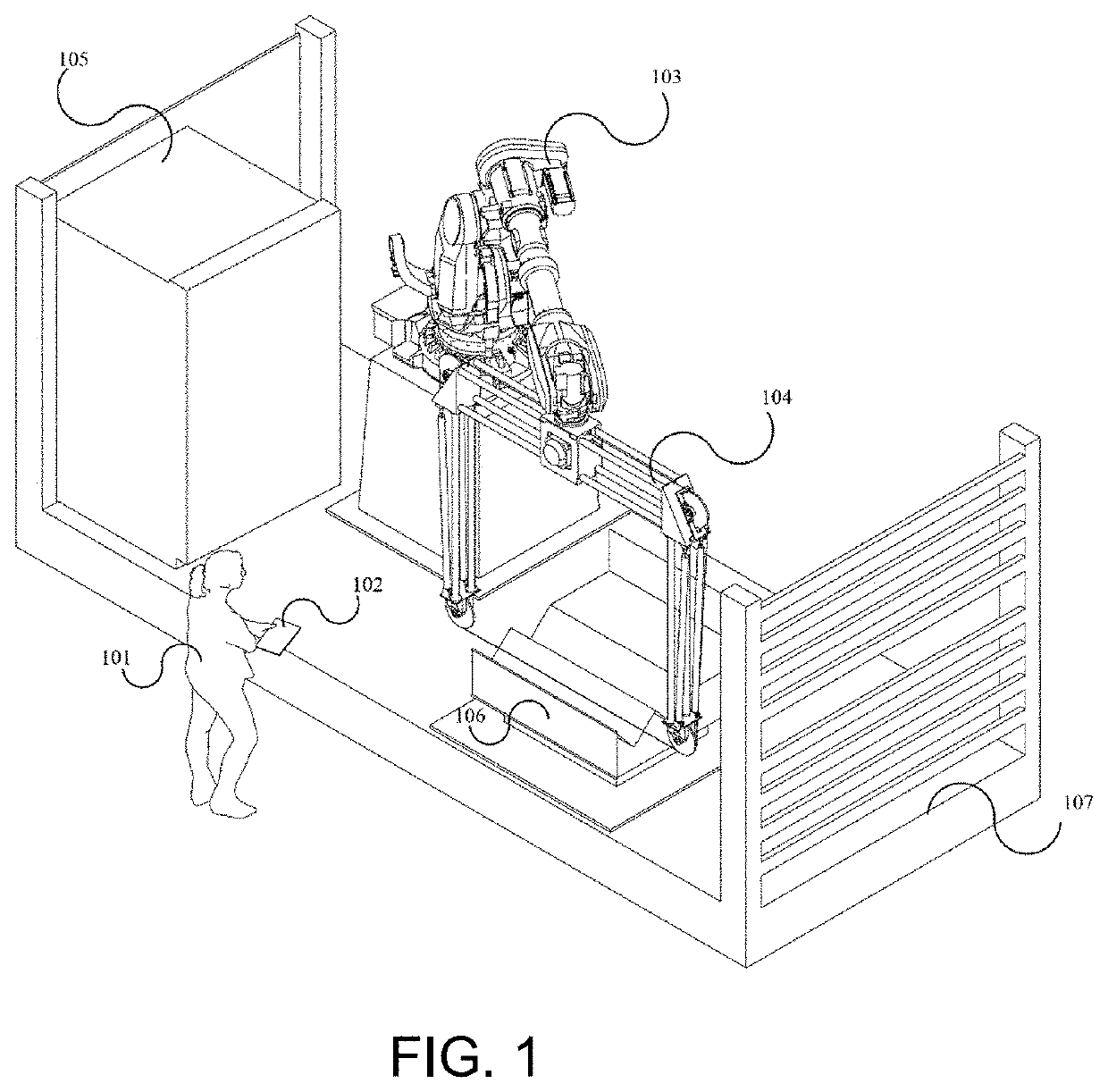
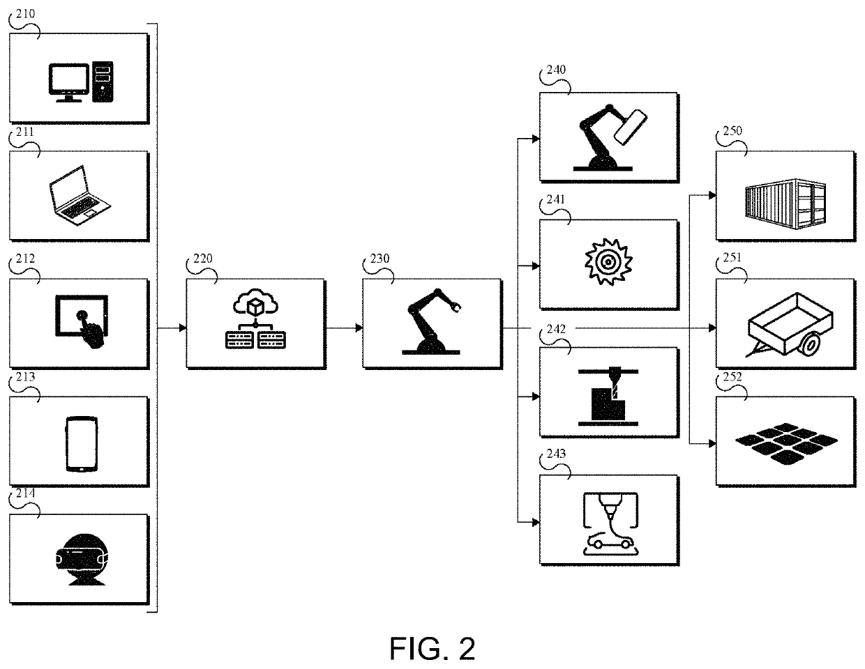
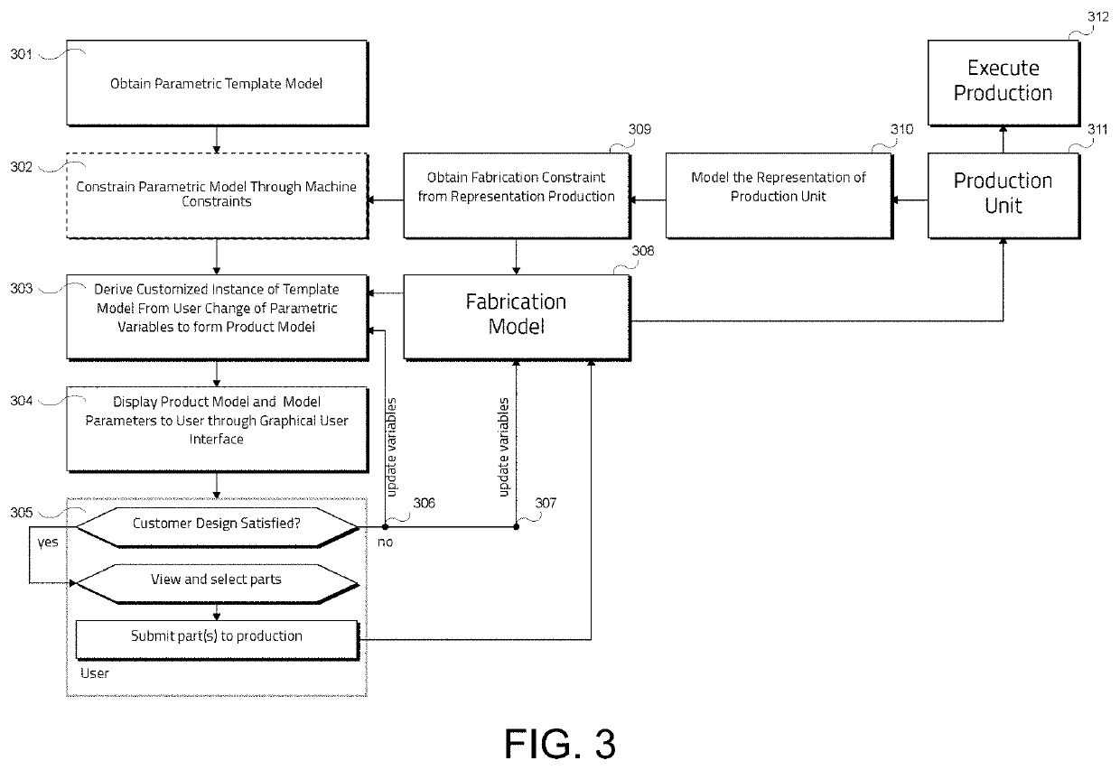

Image

  • Smart manufacturing framework
  • Smart manufacturing framework
  • Smart manufacturing framework

Examples


examples

[0110]A high-level overview of an embodiment of the system performing the method is illustrated in FIG. 7. The method starts with a user interacting with the system choosing one of a set of available actions. Examples of possible actions may be “Select”, “Model”, “Orbit”, “Pan”, “Zoom”, “Miscellaneous”, “Admin Operations”, or “Fabricate”, but other actions can form part of the system as well. These actions can be initiated via either gestures or user interface (UI) interactable elements. Any action Ai can only be performed if the system is in an allowable state. The state space on which Ai is deemed valid can be represented by Si where the constraint Si≈{ } holds true. For instance, the action “Orbit” possesses a Si={3D View}. The Action Interpreter accepts the human input, performs the validation and if found valid, propagates it to the relevant sub-system for further processing.

[0111]The Design Model Evaluator block depicted in FIG. 7 may be configured to perform several mathemati...


PUM


Abstract

The present disclosure relates to a computer-implemented method for customizing an automated product manufacturing process. It further relates to a robotic manufacturing system for manufacturing a product based on a fabrication model generated by means of the aforementioned computer-implemented method. One embodiment relates to a computer-implemented method for customizing a parametric design and manufacturing process of a physical product, the method comprising the steps of: obtaining a configurable parametric 3D product model representing a template of the physical product; customizing by a user the parametric 3D product model to provide a product instance describing the desired geometry of the physical product; automatically updating a fabrication model based on the parametric 3D product model; and optionally submitting the fabrication model to a manufacturing machine for fabricating the physical product or a mould for the physical product.

Description

CROSS-REFERENCE TO RELATED APPLICATIONS[0001]This application is the U.S. National Stage of PCT / EP2020 / 060492 filed Apr. 14, 2020, which claims priority to European Patent Application No. 19168682.3, filed Apr. 11, 2019, the content of both are incorporated herein by reference in their entirety.FIELD OF THE INVENTION[0002]The present disclosure relates to a computer-implemented method for customizing an automated product manufacturing process. It further relates to a robotic manufacturing system for manufacturing a product based on a fabrication model generated by means of the aforementioned computer-implemented method.BACKGROUND OF THE INVENTION[0003]Despite significant research efforts spanning more than four decades, the use of robotic manufacturing in global construction has to date seen no large-scale industrial adoption. As such, the international construction industry remains one of the world's largest and least digitized sectors. As a result, productivity in construction has...

Claims


Application Information

Patent Timeline
IPC IPC(8): G05B19/4097G05B19/19
CPCG05B19/4097G05B19/19G05B2219/35134G05B2219/40519G05B2219/31372G06F30/00G06F2119/18G06F2113/10Y02P90/02
Inventor SØNDERGAARD, ASBJØRNNEYTHALATH, NARENDRAKRISHNANPEDERSEN, JENSVINTER-HVIID, ANDREAS
Owner ODICO AS
Learn More