Supercharge Your Innovation With Domain-Expert AI Agents!

Method and apparatus for ionizing hydrocarbon fuels by electrolysis

a hydrocarbon fuel and electrolysis technology, applied in the direction of combustion-air/fuel-air treatment, engine components, charge feed systems, etc., can solve the problems of inefficiency of hydrocarbon fuel combustion engines and systems, uneven dispersion of fuel within the air, and prior art without the ability to adjust voltage and/or frequency for the application of different fuels, etc., to avoid damage or interference, optimal frequency and voltage, optimal combustion

Inactive Publication Date: 2022-05-26
FESENKO VASILII +1
View PDF0 Cites 0 Cited by
  • Summary
  • Abstract
  • Description
  • Claims
  • Application Information

AI Technical Summary

Benefits of technology

The present invention is a method and device to create high voltage, up to 1000 VAC at high frequencies, and apply it directly to the fuel stream through electrolysis. This creates a strong potential to fuel molecules, leading to optimal combustion and increased power output or reduced fuel consumption. The device is small in size, energy efficient, and utilizes pulse-width modulation with real-time feedback circuitry to enhance results. The technical effect is enhanced performance of the fuel system with improved combustion efficiency and reduced fuel consumption.

Problems solved by technology

Engines and systems that burn hydrocarbon fuels are well known to be inefficient, especially where the fuel is delivered in either a liquid or vapor form.
The fuel is introduced into the airstream, creating a fuel-air mixture, but the fuel is unevenly dispersed within the air.
The prior art has no means to adjust voltage and / or frequency for the application of different fuels
Another issue is that introducing high voltage potential into a premixed fuel-air mixture has the unfortunate tendency to ignite said fuel-air mixture, typically resulting in catastrophic failure of the engine.
Using DC power restricts the effectiveness of the unit due to limitations on the magnitude of voltage that can be practically applied.
DC power applications to liquid systems of engines will also tend to promote galvanic corrosion in systems where power is applied, resulting in premature failure of engines.
Finally, DC power applications lack the ability to provide real-time feedback to adjust voltages and frequencies to optimize results.

Method used


Image

  • Method and apparatus for ionizing hydrocarbon fuels by electrolysis
  • Method and apparatus for ionizing hydrocarbon fuels by electrolysis
  • Method and apparatus for ionizing hydrocarbon fuels by electrolysis

Examples


Embodiment Construction

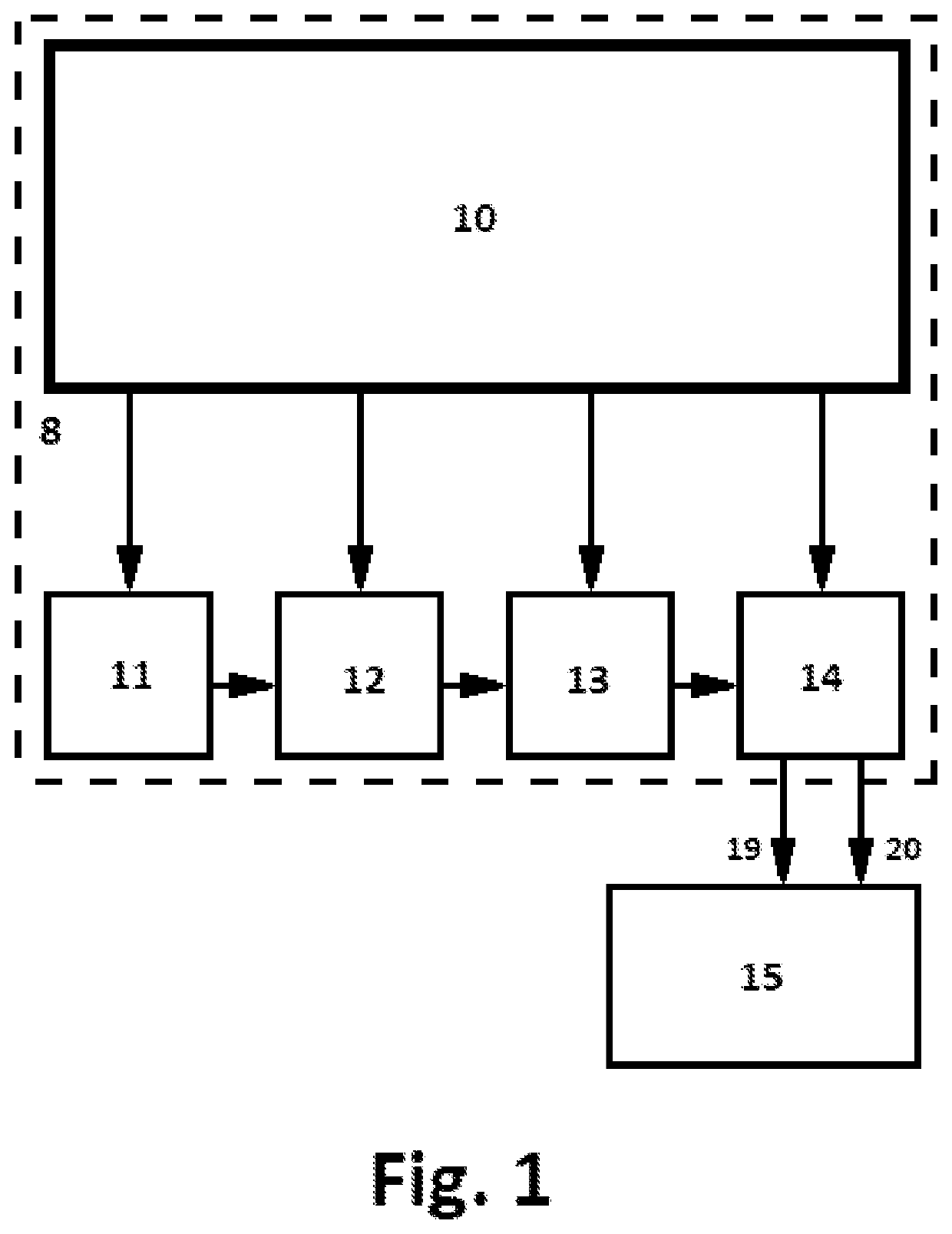
[0015]FIG. 1 block diagram: When power is supplied from the vehicle electrical system, Block 8 is turned on, the power supply filter 10 provides supply voltage to the master oscillator 11, the amplifier 12, electrical isolation transformer 13 and the voltage amplifier 14. At the same time, the master oscillator 11 generates 300 kHz square triggers amplifier 12 current and voltage. Next, the amplified signal is supplied to the galvanic isolation transformer 13 and to the diode-capacitor voltage amplifier 14. After passing through the diode-cascade circuit the now high voltage potential is applied to the fuel from the electrodes 6 and the housing 2, through connecting wires 19 and 20. Depending on the conductance and viscosity of the fuel between the electrodes and the housing, the voltage applied to the FTU will vary slightly, providing a feedback mechanism to alter the frequency and voltage applied. This enables the controller to automatically adjust applied voltage and frequency wi...


PUM


Abstract

A method for treating hydrocarbon fuel to improve the combustion characteristics of the fuel. The method comprises creating an electrolytic reaction, by applying high voltage AC through electrodes directly to the fuel. The fuel flows through the electrodes, and the applied voltage ionizes the fuel molecules, enhancing fuel distribution and improving combustion of the fuel. This results in reduced exhaust emissions, while improving both fuel economy and power. This can be used an any application where liquid or vapor hydrocarbon-based fuel is used.

Description

BACKGROUND OF THE INVENTIONField of the Invention[0001]This invention relates to a method and apparatus for treating fuel to improve the combustion characteristics of the fuel. More particularly, the invention relates to a method and apparatus for treating fluid hydrocarbon fuel by applying high AC voltage and high frequencies to electrodes that are in contact with the fuel.Description of Related Art[0002]Engines and systems that burn hydrocarbon fuels are well known to be inefficient, especially where the fuel is delivered in either a liquid or vapor form. The fuel is introduced into the airstream, creating a fuel-air mixture, but the fuel is unevenly dispersed within the air. Some fuel remains as small droplets that burn unevenly. Logically, the smaller and more dispersed the fuel droplets are, the more complete the fuel is burned. One of the ways to accomplish this is fuel ionization, where electrons are stripped off the fuel molecules, making the molecules positively charged. Th...

Claims


Application Information

Patent Timeline
IPC IPC(8): C10L1/00
CPCC10L1/00C10L2230/22C10L2290/38F02M27/04F02M27/00
Inventor FESENKO, VASILIIWOODELL, ERIC
Owner FESENKO VASILII
Features
  • R&D
  • Intellectual Property
  • Life Sciences
  • Materials
  • Tech Scout
  • Unparalleled Data Quality
  • Higher Quality Content
  • 60% Fewer Hallucinations
Learn More