Gravitational Energy Storage Device

a gravity energy and storage device technology, applied in the direction of motors, mechanical equipment, machines/engines, etc., can solve the problems of low storage capacity of batteries, high cost per kilowatt hour stored batteries, and deformation of batteries, etc., to recover energy from lowering weights, raising and lowering different weights

Pending Publication Date: 2022-05-26
WALLER DAMIEN MICHAEL TREVOR +1
View PDF6 Cites 0 Cited by
  • Summary
  • Abstract
  • Description
  • Claims
  • Application Information

AI Technical Summary

Benefits of technology

[0014]Embodiments describe a power storage system that uses a plurality of weights, which are raised and lowered in an underground hole, by a motor generator assembly, which is energized to raise the weights thus storing potential energy in the position of the weight, and which recovers energy from lowering the weights as the weights are lowered. A connection assembly, connects between the motor generator and at least one weight; where the connection assembly allows disconnecting a weight from a specific connection assembly, and using the motor generator assembly to raise and lower a different weight once the first weight is disconnected. This enables reusing the moving parts such as the motor generator assembly with multiple different weights.

Problems solved by technology

Their patented compressed air system also adds complications (eg sealing pressure) and is not required in our systems due to our designs using more of the shaft.
However, batteries have low storage capacities (less than 200 MWH).
Batteries have high cost per kilowatt hour stored.
Batteries also degrade over time.
There is a high cost to the environment on disposal of the batteries.
However, disadvantages include that water is low density, and hence its capacity is limited.
This kind of storage has a large environmental cost.
The storage depends on rainfall and can be at risk from climate change.
It can only be used in limited locations, where the water has a natural location for storage.
Building these kinds of energy storage devices can take a significant timeframes of for instance 2-5 years.
Since there needs to be a lot of area for storing the water, these can typically be done only at a large distance from cities, requiring a long power transmission.

Method used


Image

  • Gravitational Energy Storage Device
  • Gravitational Energy Storage Device
  • Gravitational Energy Storage Device

Examples


Embodiment Construction

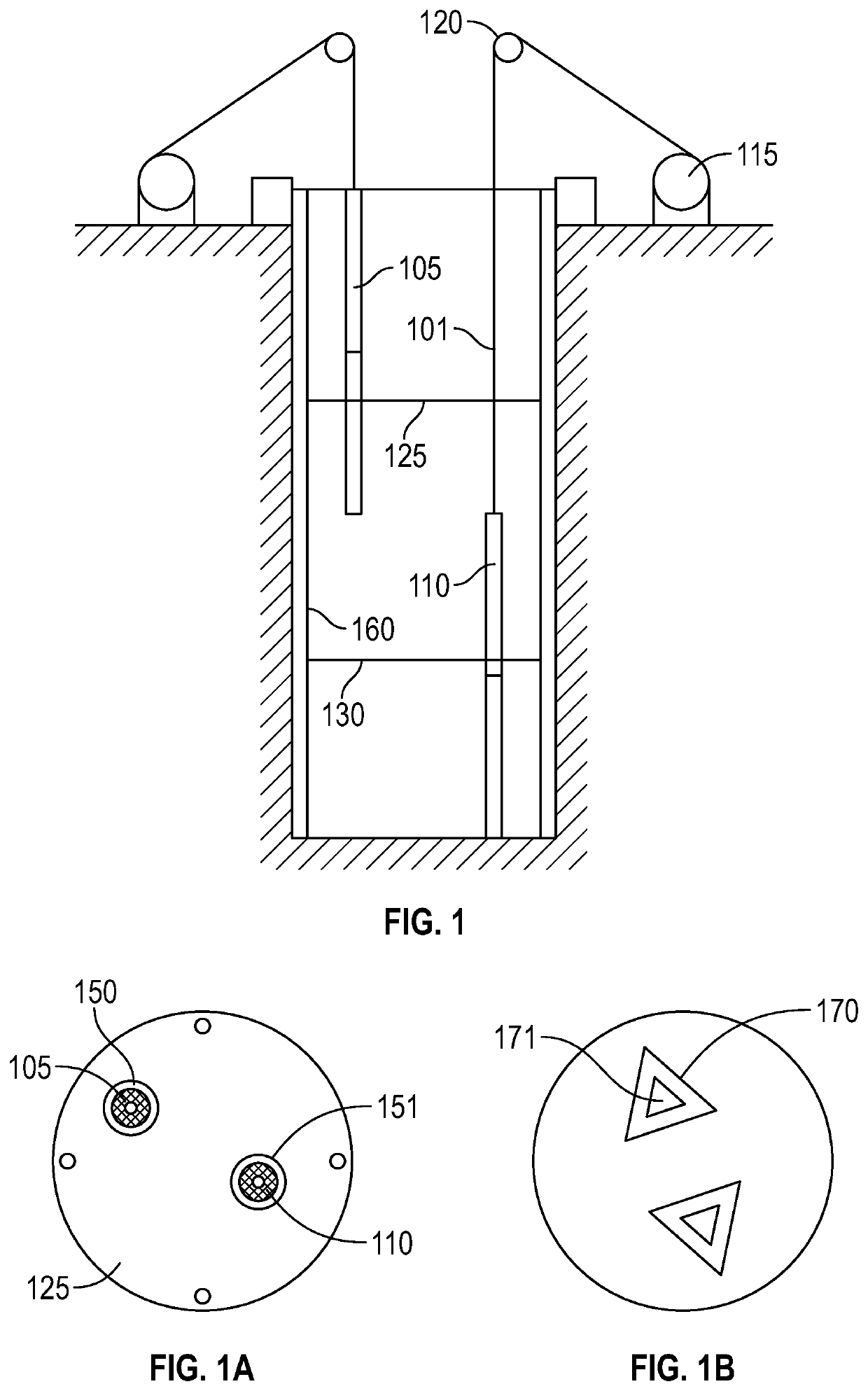
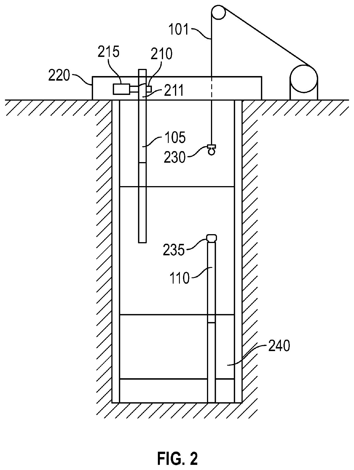
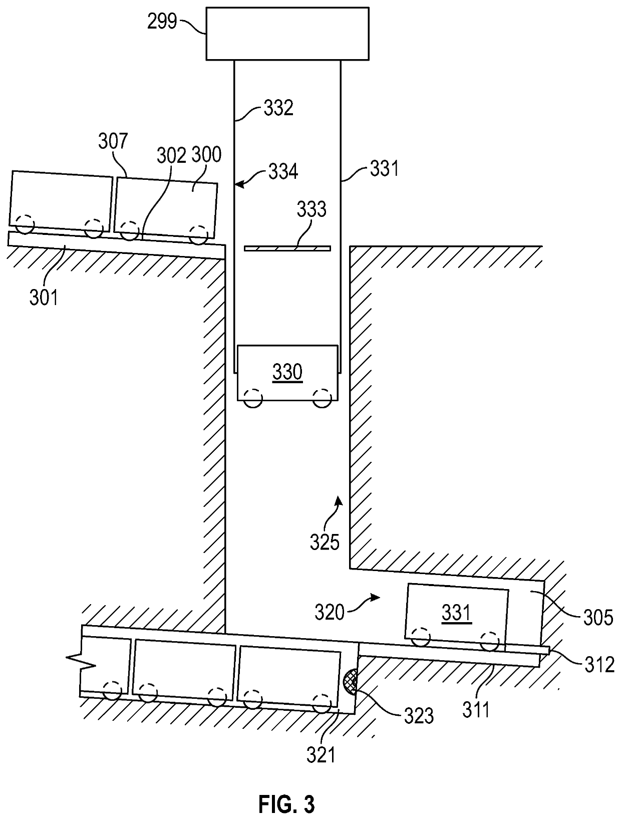
[0036]The present application describes a system using a motor / generator to lift weights to store power and to drop weights to release power.

[0037]Throughout this patent application, the terms have the following meanings.

[0038]Weight means a mass or structure, preferably made of low cost and highly dense materials.

[0039]Typical materials for weights can include steel, compacted iron ore, high density concrete, or other dense material with the cost to weight ratio which is favorable. Embodiments can use combinations of the above aaterials. For example, embodiments can use steel pipes or tanks with iron ore compacted within the steel types or tanks. Embodiments can use steel structures with formed concrete.

[0040]Weight energy transfer or WET means a system that converts the movement of the weights into energy or uses energy to move the weights to store the energy, or “charge” the system.

[0041]One such system can include cables and winches including associated gearing for moving the we...


PUM


Abstract

A power storage system that uses a plurality of weights, which are raised and lowered in an underground hole, by a motor generator assembly, which is energized to raise the weights thus storing potential energy in the position of the weight, and which recovers energy from lowering the weights as the weights are lowered. A connection assembly, connects between the motor generator and at least one weight; where the connection assembly allows disconnecting a weight from a specific connection assembly, and using the motor generator assembly to raise and lower a different weight once the first weight is disconnected. This enables reusing the moving parts such as the motor generator assembly with multiple different weights.

Description

[0001]This application claims priority from provisional application number 63 / 198,101, filed Sep. 29, 2020, the entire contents of which are herewith incorporated by reference.BACKGROUND[0002]Gravitational Energy Storage, also called GES, stores energy via lifting large weights within a shaft.[0003]GES uses off the shelf and proven components, many of which are already being used in industry. These include mine hoist systems, crane systems and winch / generators.[0004]Patent document WO2013005056A1, and WO 20180134620 by Gravitricity, describes using weights in a hole at any given time. This increases the power output.[0005]Gravitricity uses a crane system that stacks weights outside the top of the hole. This increases the energy storage capacity. Gravitricity has certain technology using a compressed air system that increases the power storage of a system that has a single weight in a hole that never comes out of the hole.[0006]Their patented compressed air system also adds complicat...

Claims


Application Information

Patent Timeline
Patent Type & Authority Applications(United States)
IPC IPC(8): F03G3/00
CPCF03G3/094
Inventor WALLER, DAMIEN MICHAEL TREVORWARD, JUSTIN LEIGH
Owner WALLER DAMIEN MICHAEL TREVOR
Why Eureka
Try Eureka