Eureka AIR delivers breakthrough ideas for toughest innovation challenges, trusted by R&D personnel around the world.

Phase alignment system and method of oscillating mirror

a phase alignment and mirror technology, applied in the direction of reflective surface testing, structural/machine measurement, instruments, etc., can solve the problems of difficult to set a high-resolution angle sensor, limited micro-galvanometer, and certain degree of dispersion, and achieve good focusing, strong beam direction, and convenient detection

Pending Publication Date: 2022-06-23
PERA
View PDF0 Cites 0 Cited by
  • Summary
  • Abstract
  • Description
  • Claims
  • Application Information

AI Technical Summary

Benefits of technology

The present invention provides a method for aligning the phase of an oscillating mirror using a simple, high-precision solution. This method does not require additional components or special devices, and can detect the state of partial overlap, mutual separation, and end-to-end connection through two specially constructed scanning patterns. The laser light source used in this invention has strong beam direction and good focusing, and the scanning line segment obtained by the beam on the projection screen has a clear boundary, making it convenient to detect the relative position of the first scan line and the second scan line. The phase alignment method of this invention is easy to apply and has high accuracy, making it suitable for use in an oscillating mirror device.

Problems solved by technology

Moreover, the phase difference is affected by factors such as the manufacturing process of the micro-galvanometer and the material inconsistency, and there is a certain degree of dispersion.
However, different from the angle sensor solution adopted by the large-size galvanometer motor, the micro-galvanometer is limited by the size, and it is difficult to set a high-resolution angle sensor.
This method requires that each micro-galvanometer device must have a one-to-one corresponding accurate phase difference parameter, which has become one of the main difficulties in the batch application of micro-galvanometer.
Therefore, the operation is difficult and the actual alignment effect is poor.
At present, in the technical field of electrically excited oscillating micro-mirrors, there is still a lack of a phase alignment method with simple solutions and high precision.

Method used


Image

  • Phase alignment system and method of oscillating mirror
  • Phase alignment system and method of oscillating mirror
  • Phase alignment system and method of oscillating mirror

Examples


Embodiment Construction

[0034]The embodiments of the present invention will be described in detail below with reference to the accompanying drawings.

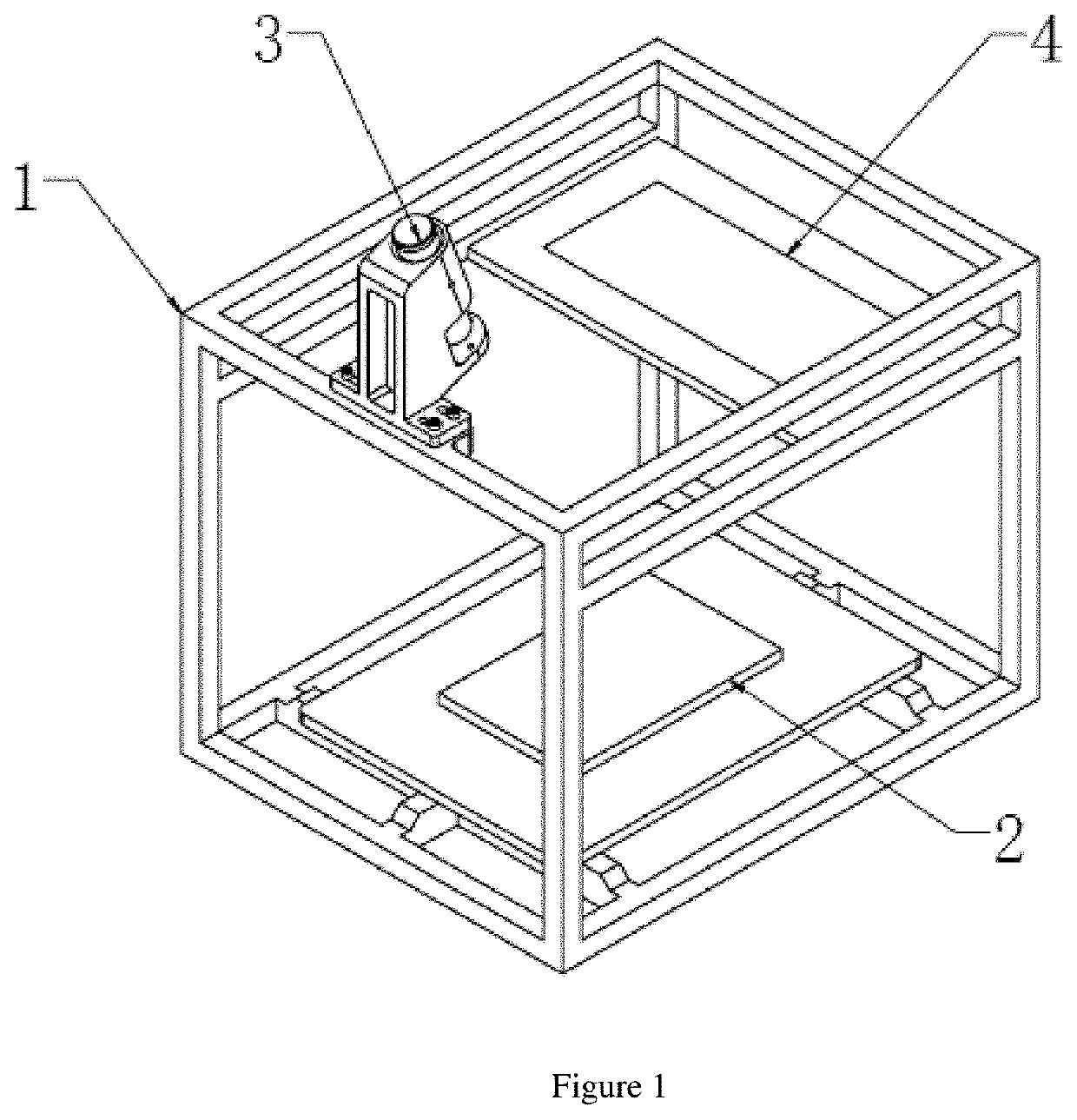
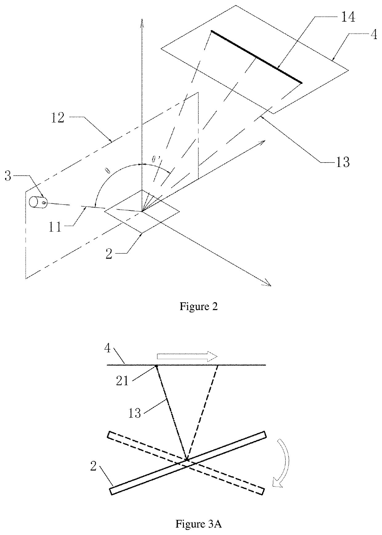
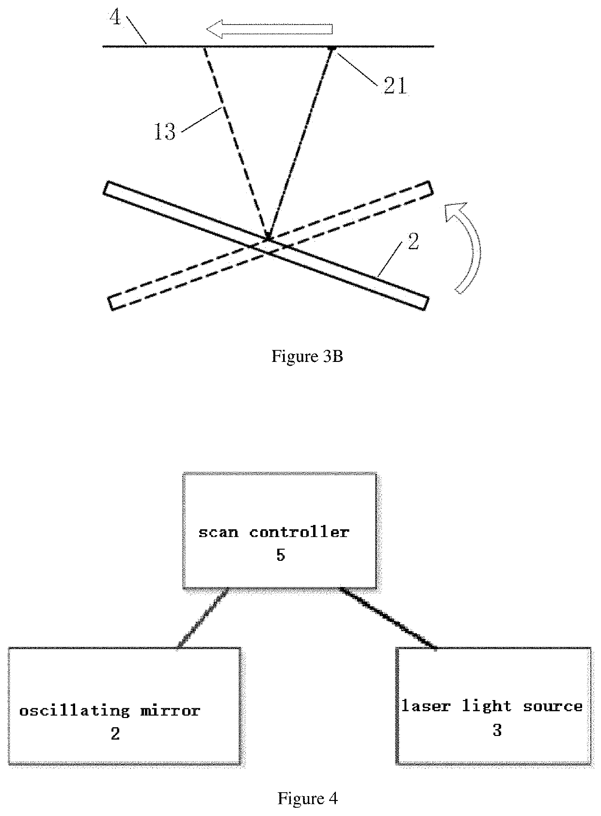
[0035]A phase alignment system of oscillating mirror, comprising: laser light source, oscillating mirror and scan controller. In one or more embodiments, as shown in FIG. 1, an oscillating mirror 2 is provided on the base of the rigid support 1, a laser light source 3 is provided on the rigid support 1, the laser beam emitted by the laser light source 3 is directed to the center position of the micro oscillating mirror 2, and illuminated on the projection plane 4 after being reflected. The projection plane 4 is parallel to oscillating mirror 2 in static state. The schematic diagram of the optical path is shown in FIG. 2. The laser beam 11 emitted by the laser light source 3 is located in the normal plane 12 drawn from the torsion axis of the oscillating mirror 2, and the reflected beam 13 reflected by the oscillating mirror 2 is directed toward the projection ...


PUM


Abstract

The present invention discloses a phase alignment system and method of oscillating mirror. The present invention utilizes the reciprocating scanning symmetry feature of the simple harmonic oscillation motion of the oscillating mirror to construct scanning pattern data with complementary pixel brightness and darkness. When the phase difference parameter applied by the scan controller is consistent with the actual phase of simple harmonic oscillation of the oscillating mirror, the scanning pattern data with complementary pixel brightness and darkness and the reciprocating motion of the oscillating mirror are accurately matched, and a perfect stitched continuous scanning line with uniform brightness is obtained on the projection plane, thereby achieving the effect of being clearly distinguishable, easy to detect, and convenient for alignment operation.

Description

TECHNICAL FIELD[0001]The invention relates to the electrical control systems and methods, and specifically to a phase alignment system and method of an oscillating mirror.BACKGROUND OF THE INVENTION[0002]With the advancement of ultra-precision manufacturing technology, miniature oscillating mirrors made by miniaturization process are constantly emerging in recent years. Among them, there are micro-galvanometer devices that are excited by pulsed voltage and driven by a periodic electrostatic field, and there are micro galvanometer devices that are driven by pulsed current and driven by a periodic magnetic field. Their oscillation frequency can reach more than 20 kilohertz, and the angular amplitude can reach more than ±25°.These devices have been used to construct a variety of optical scanning or optical imaging devices, such as automotive HUD displays, lidars, structured light three-dimensional scanners, and so on. Affected by the fact that the torsion beam structure made of silicon...

Claims


Application Information

Patent Timeline
Patent Type & Authority Applications(United States)
IPC IPC(8): G01M11/02
CPCG01M11/0207G01M11/005G02B26/105
Inventor YU, HONGXIANGWANG, KANGHENGYANG, YIJIE
Owner PERA
Why Eureka
Eureka Blog
Learn More