Phase calibration system and method for oscillating reflector

A phase calibration and mirror technology, which is applied in the direction of reflective surface testing, machine/structural component testing, instruments, etc., can solve problems such as poor calibration effect and difficult operation, and achieve simple scheme, good focus, and high-precision phase calibration Effect

Active Publication Date: 2020-10-09
PERA
View PDF4 Cites 0 Cited by
  • Summary
  • Abstract
  • Description
  • Claims
  • Application Information

AI Technical Summary

Problems solved by technology

[0004] In the absence of accurate phase difference parameters, existing engineering solutions generally detect the position deviation of the edge of the pattern projected by the micro-galvanometer to indirectly calculate the phase difference between the electrical excitation signal and the simple harmonic oscillation, or directly calculate the phase difference between the projected pattern edge Manually adjust the phase difference parameters of the projection controller until the edge positions are the same. The phase calibration effect of the above scheme not only depends on the detection accuracy of the edge position of the image, but also requires the micro-mirror to be accurately parallel and center-aligned with the projection plane. Therefore Difficult to operate, poor actual calibration
At present, in the field of electro-excited oscillating micromirror technology, there is still a lack of a simple and high-precision phase calibration method

Method used


Image

  • Phase calibration system and method for oscillating reflector
  • Phase calibration system and method for oscillating reflector
  • Phase calibration system and method for oscillating reflector

Examples


Embodiment Construction

[0034] Embodiments of the present invention will be described in detail below in conjunction with the accompanying drawings.

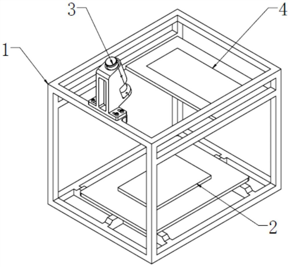
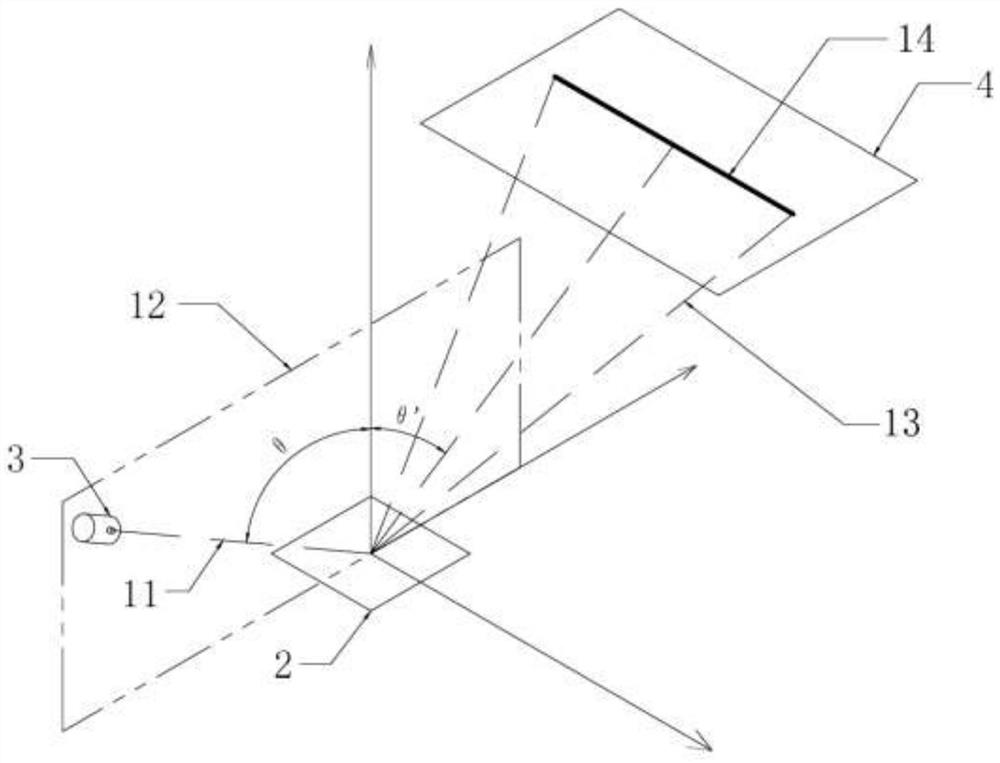
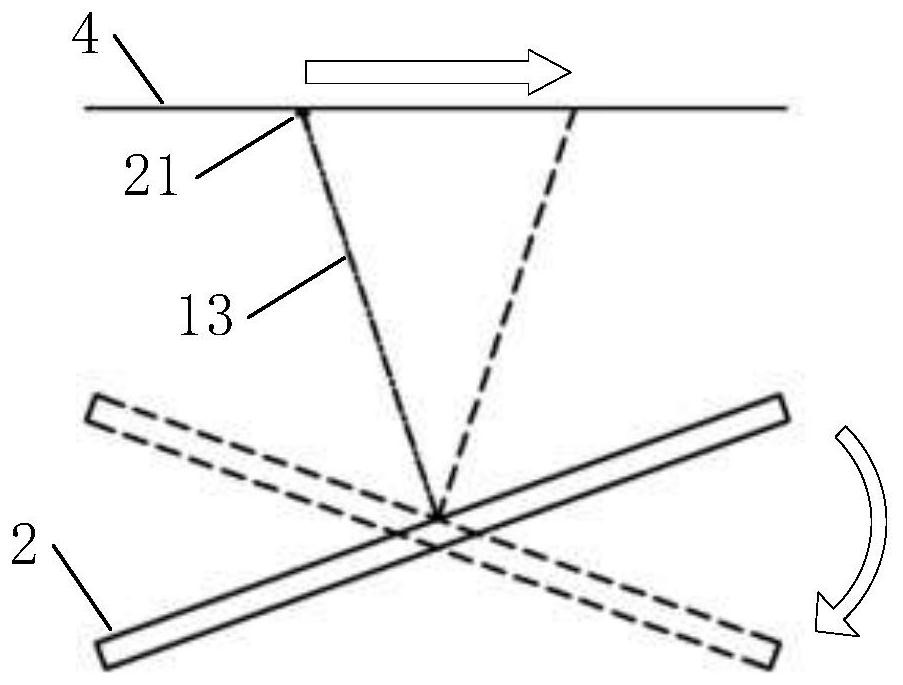
[0035] A phase alignment system for an oscillating reflector includes a laser light source, an oscillating reflector and a scanning controller. In one or more embodiments, such as figure 1 As shown, an oscillating reflector 2 is provided on the base of the rigid support 1, and a laser light source 3 is provided on the rigid support 1. The laser beam emitted by the laser light source 3 points to the center of the micro oscillating reflector 2, and irradiates after reflection. On the projection plane 4, the projection plane 4 is parallel to the oscillating reflector 2 when static; the schematic diagram of its optical path is as figure 2 As shown, the laser beam 11 emitted by the laser light source 3 is located in the normal plane 12 drawn from the torsion axis of the oscillating mirror 2 , and the reflected beam 13 reflected by the oscillating mirror 2...


PUM


Abstract

The invention discloses a phase calibration system and method for an oscillating reflector. The method comprises steps of by utilizing reciprocating scanning symmetrical characteristics of simple harmonic oscillation motion of an oscillating reflector, constructing scanning pattern data with light and shade complementation of pixels; when a phase difference parameter applied by a scanning controller is consistent with the actual phase of the simple harmonic oscillation of the oscillation type reflector, accurately matching the light and shade complementary pattern data of the pixel with the reciprocating motion of the oscillation type reflector, so that a continuous scanning line with uniform brightness after perfect splicing is obtained on a projection plane, and the effects of clearness,recognizability, easiness in detection and convenience in calibration operation are achieved.

Description

technical field [0001] The invention belongs to the class of electrical control systems and methods, in particular to a phase calibration system and method for an oscillating reflector. Background technique [0002] With the advancement of ultra-precision manufacturing technology, in recent years, miniature oscillating mirrors made by miniaturization technology are emerging, among which there are micro-vibrating mirror devices that are excited by pulse voltage and driven by periodic electrostatic fields, and some are excited by pulse current. , a micro-galvanometer device driven by a periodic magnetic field. Their oscillation frequency can reach more than 20 kHz, and the angular amplitude can reach more than ±25°. These devices have been used to build a variety of optical scanning or optical imaging devices, such as automotive HUD displays, lidar, structured light 3D scanners, etc. Affected by the torsion beam structure and material characteristics of silicon / quartz materi...

Claims


Application Information

Patent Timeline
Patent Type & Authority Applications(China)
IPC IPC(8): G01M11/02
CPCG01M11/0207G01M11/005G02B26/105
Inventor 俞红祥王康恒杨以杰
Owner PERA
Why Eureka
Try Eureka