Coercivity-enhanced iron nitride nanoparticles with high saturation magnetization

a technology of coercivity and iron nitride, which is applied in the direction of magnetic materials, solid-state diffusion coatings, magnetic bodies, etc., can solve the problems of large dilution of the overall saturation magnetization of the core/shell nanoparticle, limited the performance of permanent magnets manufactured from iron nitride nanoparticles, and difficult control

Pending Publication Date: 2022-07-07
NIRON MAGNETICS INC
View PDF0 Cites 0 Cited by
  • Summary
  • Abstract
  • Description
  • Claims
  • Application Information

AI Technical Summary

Benefits of technology

[0004]One problem that this invention solves is that iron nitride nanoparticles with high coercivity (Hci>1,000 Oe) are observed to have low saturation magnetization (MSat<180 emu / g). Microscopic examination of the nanoparticles reveals that the iron nitride nanoparticles are characterized as core / shell structures with a non-ferromagnetic iron oxide shell. Without being bound by any theory of operation, we believe that the shell enhances coercivity by magnetically decoupling adjacent nanoparticles. However, the shell thickness has always been observed to be at least 5 nm. This thickness results in a large dilution of the overall saturation magnetization of the core / shell nanoparticle. This dilution of saturation magnetization substantially limits the performance of permanent magnets manufactured from iron nitride nanoparticles.

Problems solved by technology

This thickness results in a large dilution of the overall saturation magnetization of the core / shell nanoparticle.
This dilution of saturation magnetization substantially limits the performance of permanent magnets manufactured from iron nitride nanoparticles.
Low-temperature deposition methods exist, such as electrodeposition and electroless deposition, but they are very difficult to control and are not readily capable of forming thin materials on nanoparticles.
This is because a nanoparticle with multiple, randomly oriented, crystal grains tend to be more difficult to magnetically align.

Method used


Image

  • Coercivity-enhanced iron nitride nanoparticles with high saturation magnetization
  • Coercivity-enhanced iron nitride nanoparticles with high saturation magnetization
  • Coercivity-enhanced iron nitride nanoparticles with high saturation magnetization

Examples


example 1

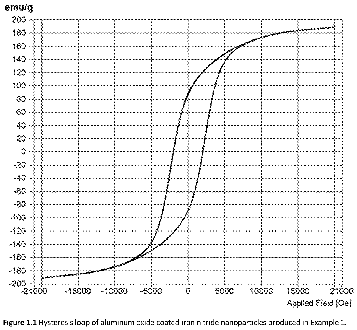
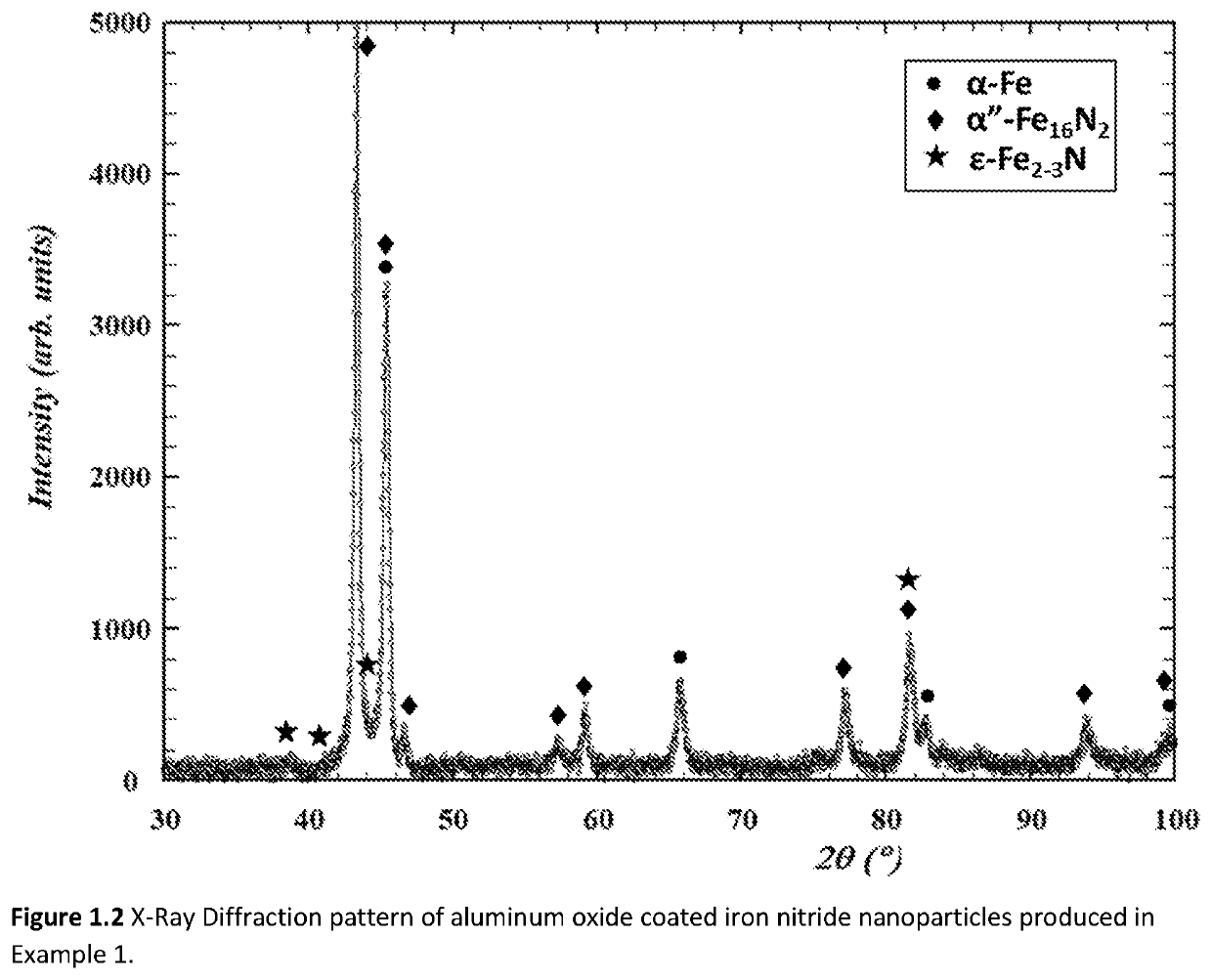
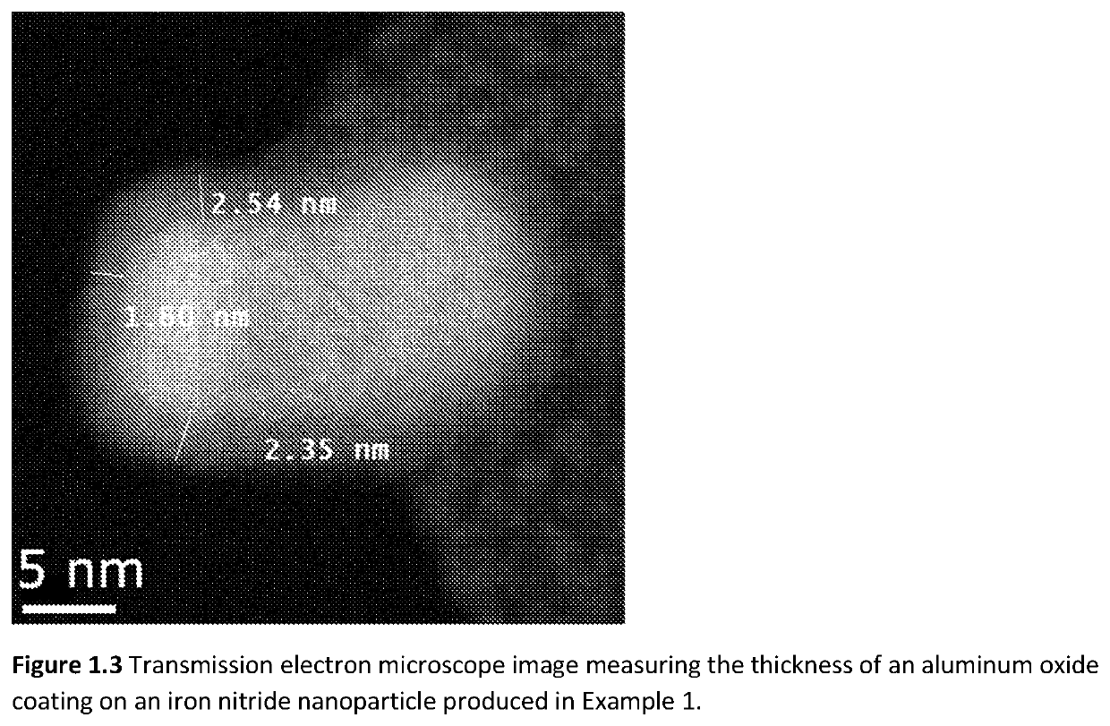
[0100]The starting materials for Example 1 were iron nitride nanoparticles prepared by reduction and nitriding of commercially procured γ-Fe2O3 nanoparticles in a 2″ diameter rotary tube furnace. A total of 9 lots of nanoparticles, each lot approximately 1.2 grams in mass, were combined together to make the starting materials for the aluminum oxide coating operation. The γ-Fe2O3 nanoparticles were first transformed into α-Fe nanoparticles by reduction in H2 gas flowing at 200 sccm (standard cubic centimeters per minute) at 335° C. for 12 hours. The α-Fe nanoparticles were subsequently transformed into iron nitride nanoparticles by flowing NH3 gas at a rate of 60 sccm at 135° C. for 22 hours. The iron nitride nanoparticles were both unloaded and stored in a nitrogen filled glovebox. Phase analysis by X-Ray diffraction indicated that the iron nitride nanoparticles were a mixture of α″-Fe16N2, α-Fe2-3N, and α-Fe. The majority of the phase fraction was α″-Fe16N2.

[0101]The aluminum oxide...

example 2

[0105]The starting materials for Example 2 were nine lots of iron nitride nanoparticles, each lot approximately 1.2 grams in mass, that were prepared in a rotary tube furnace by the same method described in Example 1. The atomic layer deposition parameters in Example 2 were also the same as Example 1, except for the fluidized bed temperature. The fluidized bed temperature in Example 2 was set to be 130° C. The hysteresis loop measured on the coated nanoparticles (FIG. 2.1) shows a saturation magnetization of 181 emu / gram and an intrinsic coercivity of 1,916 Oe. The X-Ray diffraction pattern again shows a mixture (FIG. 2.2) of α″-Fe16N2, α-Fe2-3N, and α-Fe phases. The major X-Ray diffraction peaks of each phase present in Example 2 are identified below in Table 2. Mossbauer spectroscopy indicates that the mass fraction of the α-Fe16N2 phase is 67%. The thickness of the aluminum oxide was measured to be 2.0-4.0 nm by high resolution transmission electron microscopy (FIG. 2.3 and FIG. ...

example 3

[0107]The starting materials for Example 3 were commercially procured γ-Fe2O3 nanoparticles. Prior to being loaded into the fluidized bed reaction vessel, the γ-Fe2O3 nanoparticles were sieved and the 25 μm to 53 μm sieve fraction was retained. After loading into the fluidized bed reactor, the γ-Fe2O3 nanoparticles were transformed into α-Fe nanoparticles by reducing in H2 gas flowing at 200 sccm at 315° C. for 15 hours. The α-Fe nanoparticles were then transformed into iron nitride nanoparticles by NH3 gas flowing at 120 sccm at 135° C. for 40 hours. A coating of aluminum oxide was applied on the surface of the iron nitride nanoparticles by atomic layer deposition using 9 cycles of alternating trimethylaluminum and water at 100° C.

[0108]The hysteresis loop on the coated nanoparticles (FIG. 3.2) shows a saturation magnetization of 158 emu / gram and an intrinsic coercivity of 1,798 Oe. The X-Ray diffraction pattern (FIG. 3.2) shows a mixture of the desired of α″-Fe16N2, α-Fe2-3N, and ...


PUM

PropertyMeasurementUnit
coercivityaaaaaaaaaa
thicknessaaaaaaaaaa
stability temperatureaaaaaaaaaa

Abstract

Iron nitride nanoparticles and magnet materials made from iron nitride nanoparticles are described. The iron nitride nanoparticles have a core and a shell morphology. The shell is configured to provide a means to nitride the core. The magnetic materials are characterized as having an Msat greater than about 160 emu / g and a coercivity greater than about 700 Oe.

Description

CROSS-REFERENCE TO RELATED APPLICATIONS[0001]This application claims priority to U.S. Provisional Patent Application No. 62 / 851,190, filed May 22, 2019, the disclosure of which is hereby incorporated by reference in its entirety.FIELD OF THE INVENTION[0002]The disclosed invention is in the field of compositions comprising iron nitride and magnetic materials made therefrom.BACKGROUND OF THE INVENTION[0003]Iron nitride nanoparticles have been produced for many years by controlled nitriding of iron and iron oxide nanoparticle precursors. These materials are of interest because of their potential to be manufactured into high performance, non-rare earth containing permanent magnets. To date, a commercially viable iron nitride permanent magnet has not yet been developed, partly because iron nitride nanoparticles having the α″-Fe16N2 phase with high coercivity (Hci>1,000 Oe) are observed to have low saturation magnetization (MSat<180 emu / g). Thus, there is a need to manufacture iron ...

Claims


Application Information

Patent Timeline
Patent Type & Authority Applications(United States)
IPC IPC(8): H01F1/047C04B35/58C04B35/628B22F1/054B22F1/16C23C8/26
CPCH01F1/047B22F2304/05C04B35/62813C04B35/62884C04B35/62897B22F1/054B22F1/16C23C8/26C04B2235/3852C04B2235/3272C04B2235/405C04B2235/3217C04B2235/5454C04B2235/5445C04B2235/85B22F2301/35B22F2302/25C04B35/58042C21D1/26C21D6/00H01F1/061H01F1/08
Inventor JOHNSON, FRANCISWU, YIMINGLARSON, JOHN MICHAELBLACKBURN, L. ANDERSON
Owner NIRON MAGNETICS INC
Why Eureka
Try Eureka