Check patentability & draft patents in minutes with Patsnap Eureka AI!

Buried word line structure and manufacturing method thereof

a technology of word line and manufacturing method, applied in the field of buried word line structure, can solve problems such as leakage current generation, and achieve the effect of leakage current generation

Active Publication Date: 2022-07-07
WINBOND ELECTRONICS CORP
View PDF1 Cites 0 Cited by
  • Summary
  • Abstract
  • Description
  • Claims
  • Application Information

AI Technical Summary

Benefits of technology

The patent describes a structure that reduces the electric field in a corner region around a buried word line to prevent leakage current during device operation. This is achieved by forming a barrier layer with an extension portion on the buried word line and a channel layer on the barrier layer. The channel layer extends next to the barrier layer and connects to another barrier layer around the buried word line. This results in improved device performance and stability.

Problems solved by technology

However, when a distance between the buried word line and a capacitor disposed on the substrate is too close, electrons stored in the capacitor are easily attracted by the electric field generated by the buried word line, and resulting in generation of a leakage current.

Method used


Image

  • Buried word line structure and manufacturing method thereof
  • Buried word line structure and manufacturing method thereof
  • Buried word line structure and manufacturing method thereof

Examples


Embodiment Construction

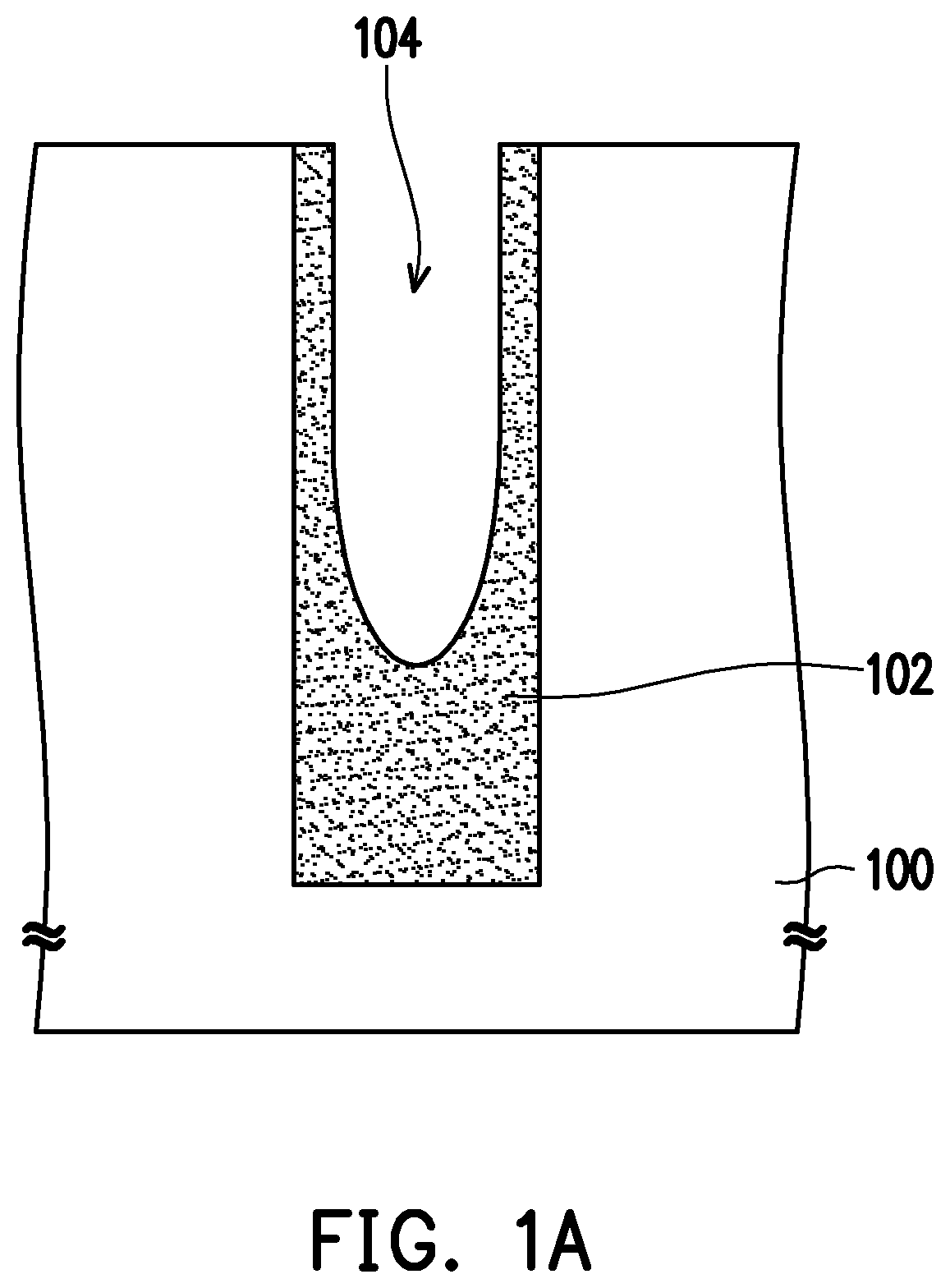
[0011]FIGS. 1A to 1G are schematic cross-sectional views of a manufacturing process of a buried word line structure according to an embodiment of the disclosure.

[0012]With reference to FIG. 1A, a substrate 100 is provided. The substrate 100 may be a semiconductor substrate. The substrate 100 is, for example, a silicon substrate. Next, a first isolation structure 102 is formed in the substrate 100. The first isolation structure 102 is a shallow trench isolation structure (STI), a material of the first isolation structure 102 is silicon nitride, but the disclosure is not limited thereto. In other embodiments, the material of the first isolation structure 102 may also be silicon oxide. Subsequently, a trench 104 is formed in the first isolation structure 102. The trench 104 is configured to define a region of a buried word line, which is formed subsequently.

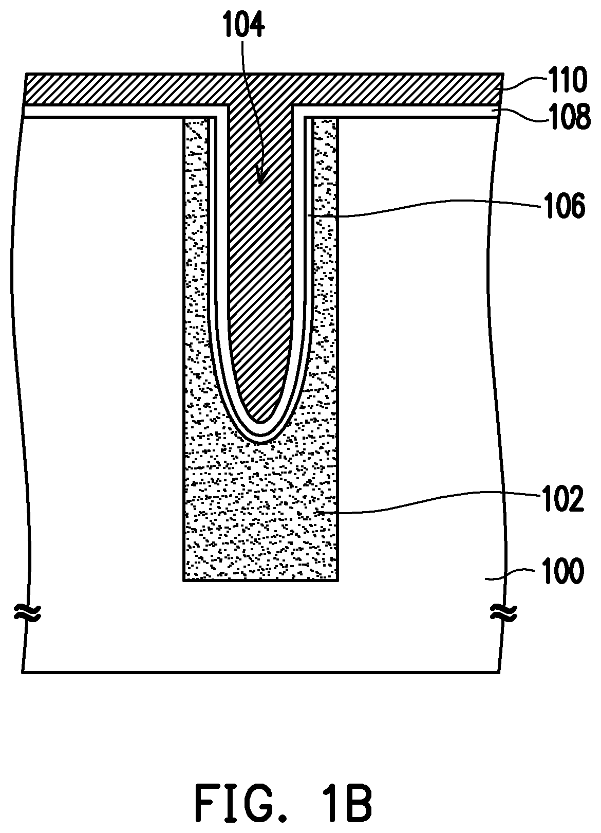
[0013]With reference to FIG. 1B, an insulation layer 106 may be formed on a sidewall and a bottom surface of the trench 104 after ...


PUM


Abstract

A buried word line structure, including a first isolation structure, a buried word line, a first barrier layer, a second barrier layer, a channel layer, and a second isolation structure, is provided. The first isolation structure is disposed in the substrate and has a trench. The buried word line is disposed on a bottom surface of the trench. The first barrier layer is disposed between the buried word line and a sidewall and the bottom surface of the trench. The second barrier layer covers a top surface of the buried word line and includes a main portion and an extension portion. The main portion is located on the buried word line, and the extension portion extends upward from periphery of the main portion. The channel layer is disposed on the first barrier layer and the second barrier layer. The second isolation structure is disposed on the channel layer.

Description

CROSS-REFERENCE TO RELATED APPLICATION[0001]This application claims the priority benefit of Taiwan application serial no. 110100475, filed on Jan. 6, 2021. The entirety of the above-mentioned patent application is hereby incorporated by reference herein and made a part of this specification.BACKGROUNDTechnical Field[0002]This disclosure relates to a semiconductor structure and a manufacturing method thereof, and in particular to a buried word line structure and a manufacturing method thereof.Description of Related Art[0003]Buried word line dynamic random access memory (DRAM) has been developed in recent years to enhance integration of DRAM, so as to speed up the operation of elements and to meet the demand of consumers for miniaturized electronic devices.[0004]In general, the buried word line may be disposed in the isolation structure. However, when a distance between the buried word line and a capacitor disposed on the substrate is too close, electrons stored in the capacitor are e...

Claims


Application Information

Patent Timeline
IPC IPC(8): H01L27/108H01L29/423
CPCH01L27/10823H01L29/4236H01L27/10891H01L27/10876H10B12/34H10B12/488H10B12/053
Inventor LIN, CHANG-HUNG
Owner WINBOND ELECTRONICS CORP
Features
  • R&D
  • Intellectual Property
  • Life Sciences
  • Materials
  • Tech Scout
  • Unparalleled Data Quality
  • Higher Quality Content
  • 60% Fewer Hallucinations
Learn More