
Intravascular optical device

an intravascular optical and micro-catheter technology, applied in the field of intravascular optical devices, can solve the problems of increasing medical complications, increasing treatment costs, and prolonging procedure tim

Pending Publication Date: 2022-07-21
KONINKLJIJKE PHILIPS NV
View PDF0 Cites 0 Cited by
  • Summary
  • Abstract
  • Description
  • Claims
  • Application Information

AI Technical Summary

Benefits of technology

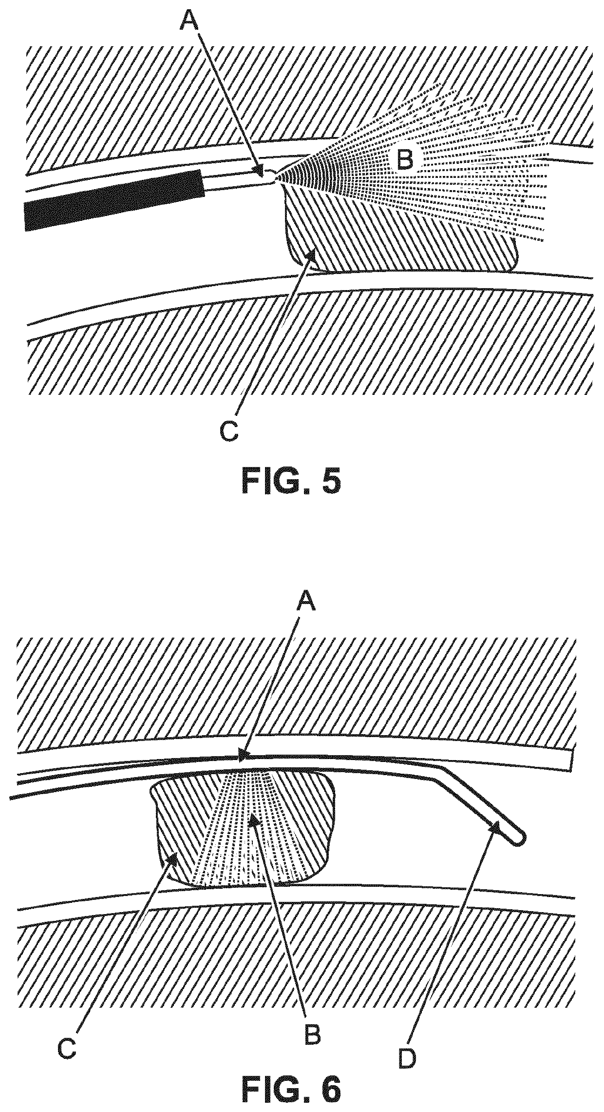
The patent describes an improved device for investigating blood clots in the vasculature. The device uses optical radiation to interrogate the vascular structure and determine the location and type of blood clot present. The device emits optical radiation from multiple angles around the device, allowing for efficient and effective interrogation without the need to rotate the guidewire. This approach also allows for the discrimination of different types of blood clots and the determination of the correct thrombectomy device to remove the clot, reducing treatment time, cost, and patient risk.

Problems solved by technology

Achieving first-time-right treatment is critical in thrombectomy because the time window available for treatment is short.
Choosing the wrong treatment device can necessitate additional attempts to remove the blood clot, thereby lengthening the procedure time.
Choosing the wrong device, and thereby necessitating the use of a subsequent different may therefore lead to an increase in medical complications as well as increased treatment cost.
The issues include the following: i) clots that are rich in red blood cells may be fragile and have a risk of clot break-up ii) clots that are rich in Fibrin may have a consistency that makes them difficult to grasp with a thrombectomy device; iii) about 15% of clots resist thrombectomy.
If left untreated, or if treated with an incorrect treatment device, a mobilized peripheral venous blood clot may for example be transported to the lung and trigger further medical complications.

Method used


Image

  • Intravascular optical device
  • Intravascular optical device
  • Intravascular optical device

Examples


Embodiment Construction

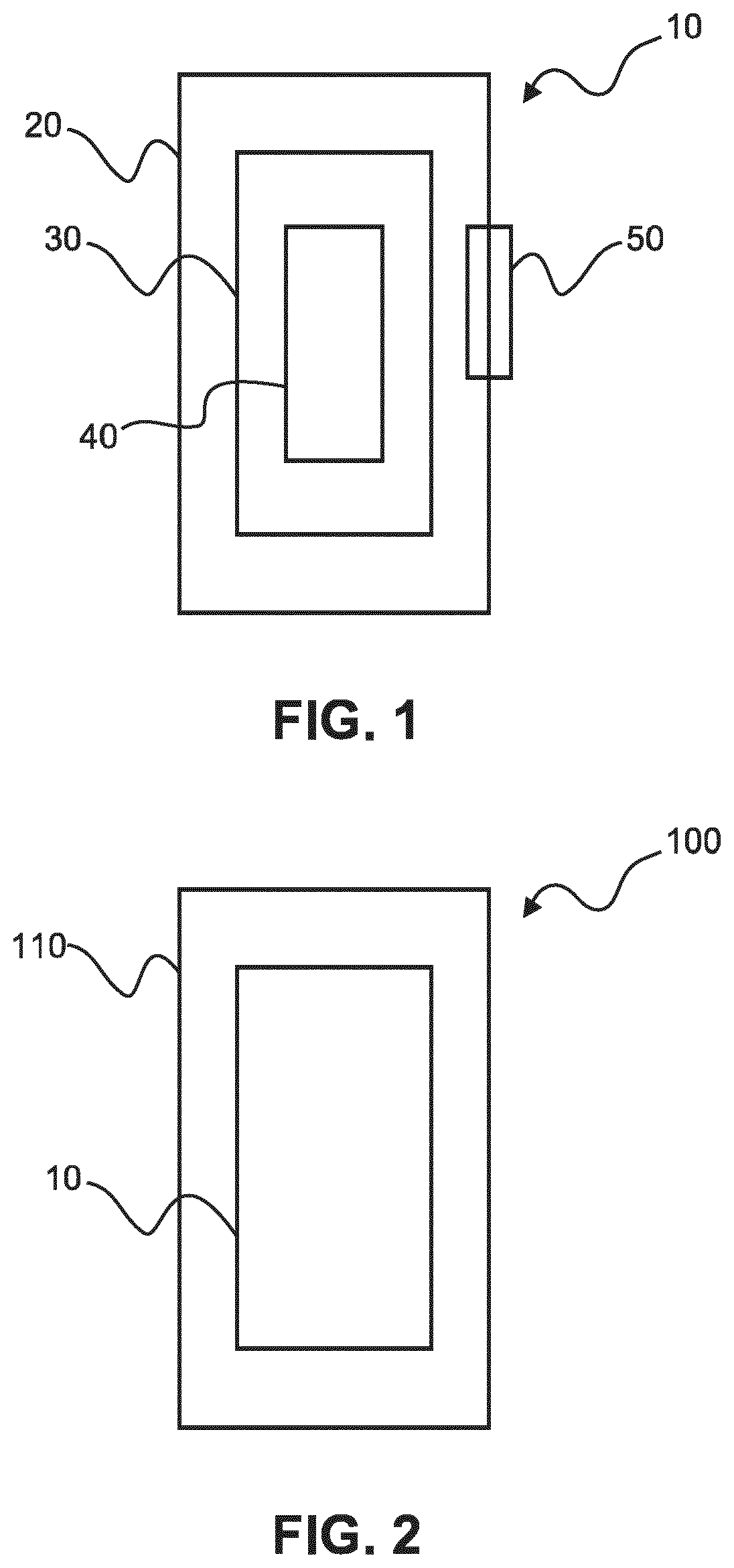
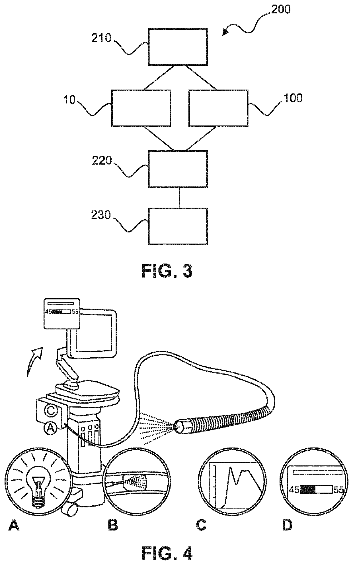
[0099]FIG. 1 shows an example of an intravascular device 10. The device comprises an elongate member 20, an optical fiber 30, and at least one optical interaction element 40. At least a part of the elongate member is configured to be inserted into a part of a vascular system of a patient. At least a part of the optical fiber is located within the elongate member. The optical fiber is configured to transmit optical wavelength radiation. The intravascular device is configured to emit optical wavelength radiation out of the elongate member in at least two optical radiation beams for being scattered and / or reflected by a portion of the vascular system. The emission of the at least two optical radiation beams comprises interaction of the transmitted optical wavelength radiation with the at least one optical interaction element. The intravascular device is configured to collect at least some of the scattered and / or reflected optical wavelength radiation and couple the at least some of the...


PUM


Abstract

The present invention relates to an intravascular device (10). The device comprises an elongate member (20), an optical fiber (30), and at least one optical interaction element (40). At least a part of the elongate member is configured to be inserted into a part of a vascular system of a patient. At least a part of the optical fiber is located within the elongate member. The optical fiber is configured to transmit optical wavelength radiation. The intravascular device is configured to emit optical wavelength radiation out of the elongate member in at least two optical radiation beams for being scattered and / or reflected by a portion of the vascular system. The emission of the at least two optical radiation beams comprises interaction of the transmitted optical wavelength radiation with the at least one optical interaction element. The intravascular device is configured to collect at least some of the scattered and / or reflected optical wavelength radiation and couple the at least some of the scattered and / or reflected optical wavelength radiation into the optical fiber comprising utilization of the at least one optical interaction element.

Description

FIELD OF THE INVENTION[0001]The invention relates to an intravascular device, an intravascular microcatheter and guidewire device, an intravascular investigation system, a method of intravascular investigation with an intravascular investigation system and to a computer program element. The intravascular device may for example be a guidewire, a catheter or a microcatheter.BACKGROUND OF THE INVENTION[0002]The general background of the invention is blood clots, and in particular the provision of information to support its treatment, for example by thrombolysis or thrombectomy. Ischemic stroke is a common cause of death in the developed world and the leading cause of acquired neurological disability. In high-income countries, a substantial increase in the number of individuals affected by stroke is expected due to increasing life expectancy.[0003]WO2016 / 205576A1 describes a beam-shaping optical system suitable for use with optical coherence tomography having a beam-shaping insert havin...

Claims


Application Information

Patent Timeline
Patent Type & Authority Applications(United States)
IPC IPC(8): A61B5/00A61B5/02
CPCA61B5/0084A61B5/02007A61B5/4869A61B1/3137A61B1/07A61B5/0075
Inventor MUELLER, MANFREDBABIC, DRAZENKOLUCASSEN, GERHARDUS WILHELMUSKURANE, ADITEE
Owner KONINKLJIJKE PHILIPS NV
Learn More