Profile chill for forming a cast device

a technology of forming a cast device and a chilling device, which is applied in the direction of manufacturing tools, foundry patterns, foundry moulding apparatus, etc., can solve the problems of affecting the service life of the cast device, affecting the tensile strength and fatigue strength, and achieving the spacing of dendrite arms in the sand cast block

Inactive Publication Date: 2022-08-04
GM GLOBAL TECH OPERATIONS LLC
View PDF2 Cites 0 Cited by
  • Summary
  • Abstract
  • Description
  • Claims
  • Application Information

AI Technical Summary

Problems solved by technology

Excess dendrite lengths, orientations, and configurations may negatively affect tensile strength and fatigue strength, thus affecting the service life of the cast devic...

Method used


Image

  • Profile chill for forming a cast device
  • Profile chill for forming a cast device
  • Profile chill for forming a cast device

Examples


Embodiment Construction

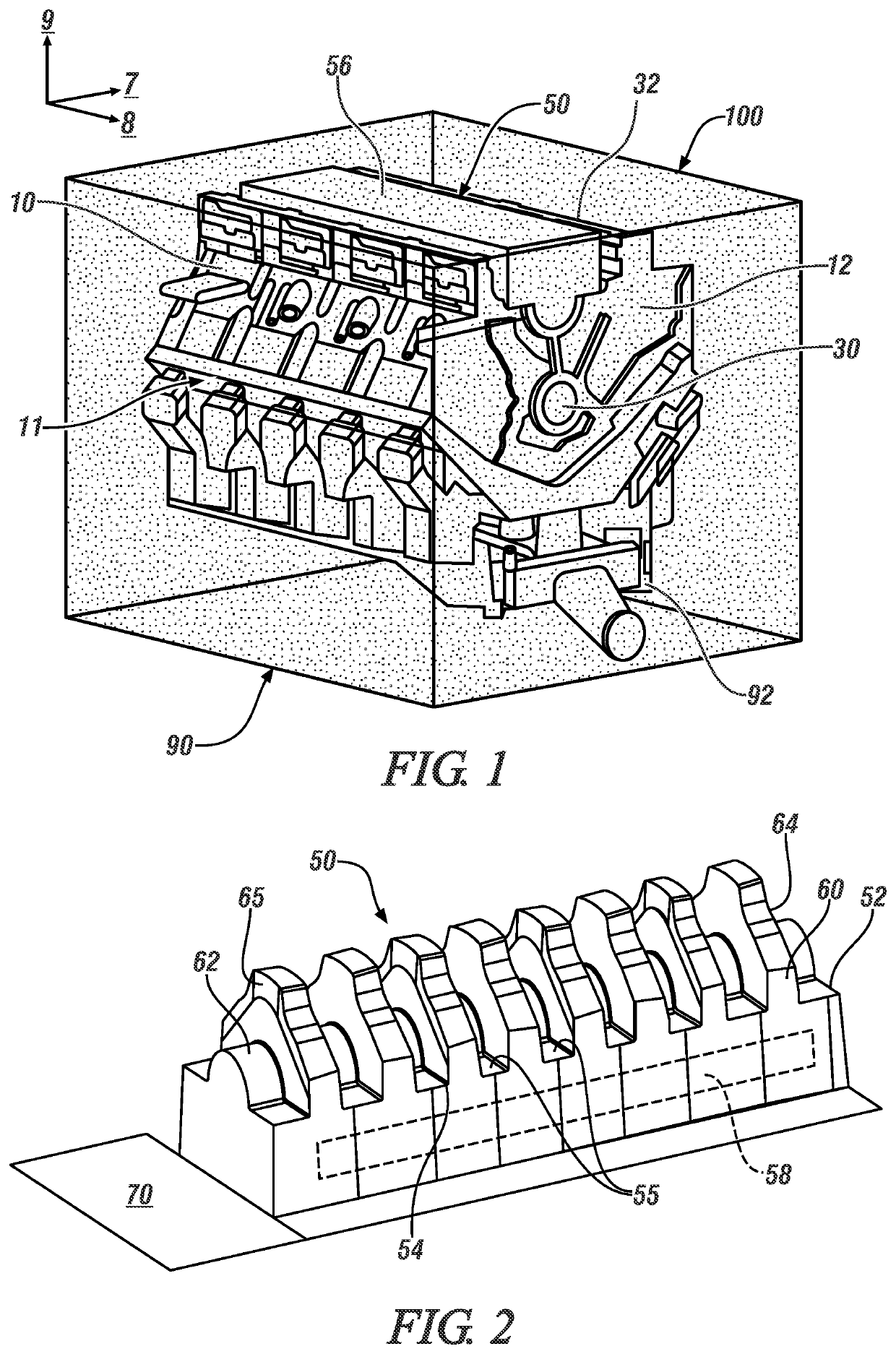
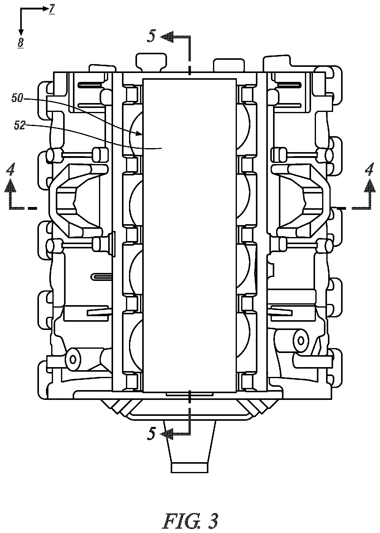
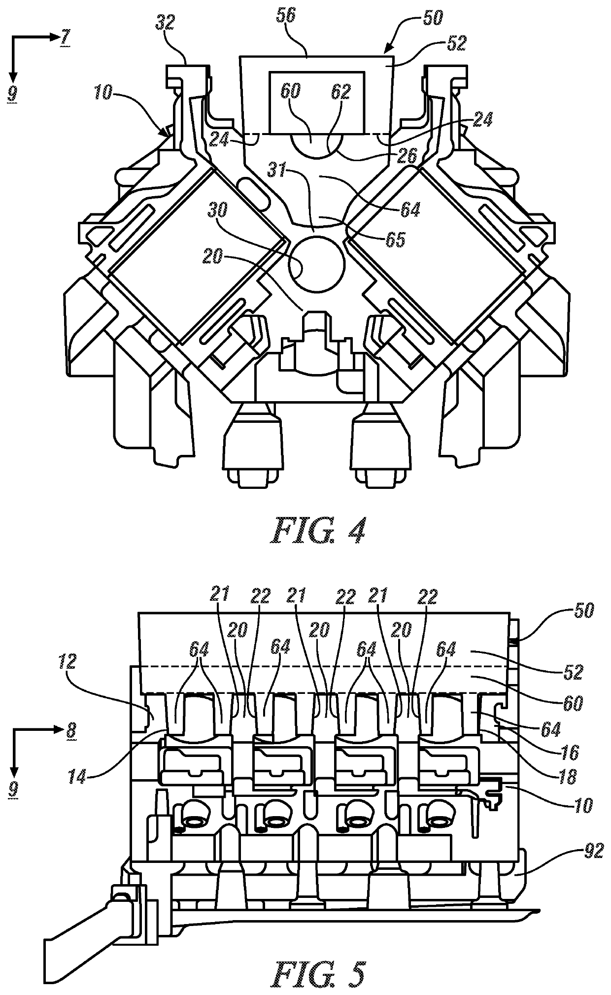
[0032]The components of the disclosed embodiments, as described and illustrated herein, may be arranged and designed in a variety of different configurations. Thus, the following detailed description is not intended to limit the scope of the disclosure, as claimed, but is merely representative of possible embodiments thereof. In addition, while numerous specific details are set forth in the following description in order to provide a thorough understanding of the embodiments disclosed herein, some embodiments can be practiced without some of these details. Moreover, for the purpose of clarity, certain technical material that is understood in the related art has not been described in detail in order to avoid unnecessarily obscuring the disclosure. For purposes of convenience and clarity, directional terms such as top, bottom, left, right, up, over, above, below, beneath, rear, and front, may be used with respect to the drawings. These and similar directional terms are not to be const...


PUM

PropertyMeasurementUnit
Electrical conductoraaaaaaaaaa

Abstract

A mold package for forming a cast device such as an engine block is described. The mold package includes a profiled chill and a mold core assembly that is disposed on the profiled chill. The mold core assembly defines a plurality of bulkheads of the engine block. The profiled chill includes a first chill portion having a second chill portion and a plurality of third chill portions arranged thereon, wherein the second chill portion is a semicylindrical element. The third chill portions are arranged to be adjacent to the plurality of bulkheads of the engine block.

Description

INTRODUCTION[0001]In a sand casting process, an expendable mold package is assembled from a plurality of resin-bonded sand cores that define internal and external surfaces of a device, wherein each of the sand cores may be formed by blowing resin-coated foundry sand into a core box and curing it therein. One example includes a sand casting process for an internal combustion engine block.[0002]In one embodiment, the mold assembly method involves positioning a base core on a surface and building up or stacking separate mold elements to shape such casting features. When casting an internal combustion engine block, elements may include sides, ends, valleys, water jackets, cam openings, and a crankcase of the cylinder block, with additional cores being present depending on the engine design.[0003]Removal of thermal energy from liquified metal in a mold package is an important consideration in the foundry process. Rapid solidification and cooling of the cast device promotes a fine grain s...

Claims


Application Information

Patent Timeline
IPC IPC(8): B22C9/06B22C9/22
CPCB22C9/065B22C9/22B22C9/103B22D15/00B22C9/10B22D15/02
Inventor MUNIKAMAL, TIRUTTANISELA, BALA KRISHNAWANG, QIGUIKAVANAGH, SCOTT A.CELLI, GUYCHOUDHARY, LOKESH
Owner GM GLOBAL TECH OPERATIONS LLC
Why Eureka
Try Eureka