Artificial intelligence-based robotized smart laser ablating systems for multi-dimensional objects

a multi-dimensional object and artificial intelligence technology, applied in the field of laser ablation, can solve the problems of corrosive and aggressive to many types of surfaces, difficult to remove contaminants from cement, concrete and bricks, and high cost of cleaning up chemically contaminated structures

Pending Publication Date: 2022-08-04
6684327 CANADA INC
View PDF0 Cites 1 Cited by
  • Summary
  • Abstract
  • Description
  • Claims
  • Application Information

AI Technical Summary

Benefits of technology

[0031]In another of its aspects, there is provided at least one sensor for detecting the characteristics of the generated laser-induced breakdown spectra of a substrate material, and controlling the output power of the laser power system, such that the settings of the laser system are caused to adapt to match the surface requirements for better quality assurance.
[0032]Advantageously, the robotized smart laser ablating system employs artificial intelligence, and minimizes human intervention and decision-making by users; and also reduces errors prevalent in prior art laser ablating systems, especially when cleaning complex structures. The robotized smart laser ablating system is capable of maintaining the focus of the laser beam on the material being cleaned, and maintaining the laser critical distance from the laser head to the material. Furthermore, the substance on the surface material to be removed and the material to be kept intact are determined automatically, including the laser damage threshold of the material to be cleaned. The cleaning process is inspected at predefined intervals, or after each laser pass to determine that the quality requirements are met, and also determine when to end the cleaning process once the cleaning objectives and desired quality have been achieved. In addition, the shape and the orientation of the object to be cleaned are recognized and the robotic positioning system sends commands to the laser head to maneuver about the object to effect the cleaning. The robotized smart laser ablating system also comprises a cognitive element capable of self-learning using knowledge gained from previous cleaning sessions, and can thereby optimize the ablation process or make predictions about the ablation process; and can also change laser settings on the fly in order to adapt to the dynamic conditions associated with the ablation event.

Problems solved by technology

Removing contaminants off cement, concrete and brick may be especially challenging since the surfaces may include cracks and pores in which the contaminants may reside.
Cleaning up chemical-contaminated structures can be difficult, costly, and time-consuming.
For one thing, most preferred methods employ other chemicals, like bleach solutions, which can be corrosive and aggressive to many types of surfaces.
However, most of these methods produce a substantial amount of secondary waste and require complex external control and deployment systems.
One of the challenges with all the above decontamination methods is that there is a wide range of radioactive waste (including liquid and solid wastes) as well the technics range in labour costs.
Several laser ablating systems have been proposed to remove a variety of layers such as paint, rust, nuclear contamination, from different substrate materials, however, these systems available on the market have basic functionalities and can only be operated by properly trained professionals, such as engineers or technicians.
Accordingly, these prior art systems require substantial human intervention, since all the decision-making associated with the ablation process must be performed by the trained professionals.
Another drawback of existing systems is the challenge of manually maintaining the focus of the laser on the material being cleaned, and maintaining the laser head at a critical distance from the substrate material.
Other issues include: the need to determine laser parameters for a particular material, often via trial and error; the inability by the existing systems to determine the coating characteristics on the surface material and the underlying substrate material to be kept intact; the inability to self-inspect the cleaning performed by the laser after each pass, or after a cleaning session for quality control purposes; and the inability to decide when to stop cleaning; the inability to calculate the laser damage threshold of the material to be cleaned; the inability to recognize shape of the object to be cleaned; the inability to accumulate knowledge and learn from previous cleaning sessions; the inability to change laser settings on the fly; and the lack of self-learning by the system to optimize the ablation process or make predictions about the ablation process.
These factors, among others, have contributed to the rather slow adoption of this technology in the market.

Method used


Image

  • Artificial intelligence-based robotized smart laser ablating systems for multi-dimensional objects
  • Artificial intelligence-based robotized smart laser ablating systems for multi-dimensional objects
  • Artificial intelligence-based robotized smart laser ablating systems for multi-dimensional objects

Examples


Embodiment Construction

[0041]Various embodiments of the disclosure are discussed in detail below. While specific implementations are discussed, it should be understood that this is done for illustration purposes only. A person skilled in the relevant art will recognize that other components and configurations may be used without parting from the spirit and scope of the disclosure. Like reference numerals are used to designate like parts in the accompanying drawings.

[0042]The detailed description provided below in connection with the appended drawings is intended as a description of the present examples and is not intended to represent the only forms in which the present example may be constructed or used. However, the same or equivalent functions and sequences may be accomplished by different examples.

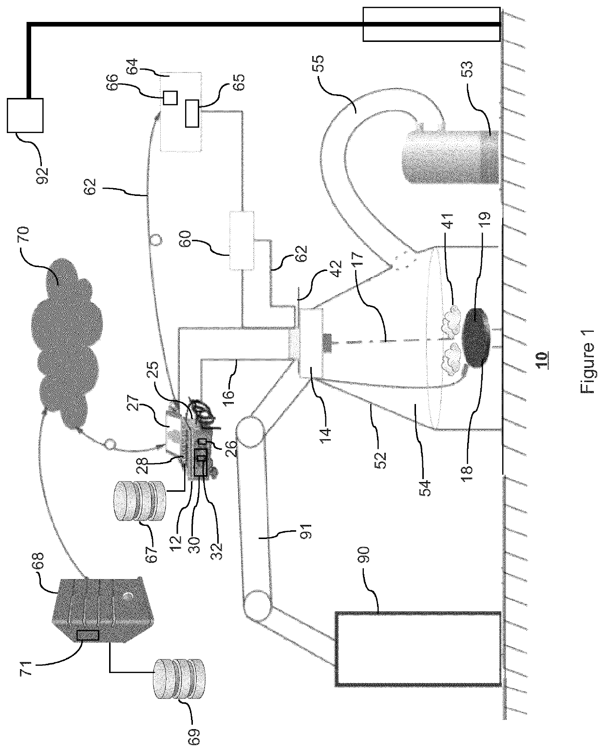
[0043]FIG. 1 shows a laser ablating system, generally identified by numeral 10, in an exemplary embodiment. Laser ablating system 10 comprises laser 12 coupled to laser ablating head 14 via fibre optic cable...


PUM

PropertyMeasurementUnit
frequencyaaaaaaaaaa
sizeaaaaaaaaaa
frequenciesaaaaaaaaaa

Abstract

A system for ablating a predetermined area of a substrate material, the system comprising: a processor; a computer readable medium comprising at least one first set of program instructions associated with the ablating protocol stored thereon, the ablating protocol comprising calibration parameters; a laser head associated with a laser power controller for generating a laser pulse having a wavelength, pulse width and output level based on the calibration parameters, wherein the laser pulse is transmitted to the laser head having an optical assembly to shape and focus a beam of the laser pulse on the substrate material; wherein the laser pulse impinges the substrate material and the layer material and emits a plasma plume and sound; sensor to capture light emitted by the plasma plume and sound emitted during the ablation event; and detector means to capture emitted light of the plasma plume associated with the ablation event.

Description

FIELD OF INVENTION[0001]The present disclosure relates to laser ablation, more particularly it relates to employing a laser to remove dirt or an undesired layer from a surface of a substrate material.BACKGROUND[0002]In the nuclear industry various methods are used for oxidized surface decontamination, and removal of a deposited layer with radioactive materials from metallic surfaces or building materials, such as cement, concrete and brick, which are extremely porous. Removing contaminants off cement, concrete and brick may be especially challenging since the surfaces may include cracks and pores in which the contaminants may reside. Cleaning up chemical-contaminated structures can be difficult, costly, and time-consuming. For one thing, most preferred methods employ other chemicals, like bleach solutions, which can be corrosive and aggressive to many types of surfaces. As an example, several methods of decontamination implement concrete scabbling and oxide layer removal, such as, w...

Claims


Application Information

Patent Timeline
Patent Type & Authority Applications(United States)
IPC IPC(8): B23K26/03G06N5/02B23K26/12B23K26/16B23K26/36B23K26/0622G01N21/71
CPCB23K26/03G06N5/022B23K26/127B23K2103/50B23K26/36B23K26/0622G01N21/718B23K26/16G01S11/14G21F9/28B23K26/032G01N2021/8416G01S2205/01G21F9/005
Inventor LAVOIE, STEEVEABOUSEIF, MOHAMEDJAMAL, BESHARI
Owner 6684327 CANADA INC
Why Eureka
Try Eureka