An alkaline flow battery assembly

a technology of alkaline flow and battery assembly, which is applied in the field of alkaline flow battery assembly, can solve the problems of corrosive vanadium electrolytes that are not environmentally friendly, csms are expensive, and csms are the most expensive element in the electrochemical reactor, and achieves the effects of reducing cost, increasing current density, and reducing the conductivity of microporous separators

Inactive Publication Date: 2022-08-11
ENERGY STORAGE SOLUTIONS SL
View PDF2 Cites 0 Cited by
  • Summary
  • Abstract
  • Description
  • Claims
  • Application Information

AI Technical Summary

Benefits of technology

[0009]The present invention is based on the use of cheap microporous separators (MPSs), instead of expensive CSMs, will result in remarkable decrease in cost. In addition, the conductivity of Microporous separator is expected to be much higher than that of CSMs in alkaline media, which will allow the battery to be operated at higher current densities. However, the crossing of species over microporous separators is not selective to cations, but also allows active redox species to diffuse through microporous separators driven by concentration gradient of active species between the two compartments. as a result, the installed energy capacity of the battery will gradually decrease falling below specifications relatively fast.
[0010]The present invention proposes the combination of identical redox electrolytes composed of two electro-active species and microporous separators. The use of identical redox electrolytes (IREs) in the two compartments will cancel the concentration gradient of active species that drives diffusion across the microporous separators. In addition, IREs will allow balancing of electrolyte, which is currently another limitation in alkaline flow batteries. So, it is possible to reach a battery with cycle-life.
[0011]The invention brings three main advantages over the state-of-the-art in alkaline flow batteries: (a) Cost of the electrochemical reactor is remarkable decreased by using MPSs, which are two-order of magnitude cheaper than currently used CSMs; (b) the maximum operating current density is also increased due to the higher ionic conductivity of MPSs in alkaline media. An increase in current density leads to smaller size of the electrochemical reactor and, thus, lower cost; and (c) the maximum operating temperature is increased. CSMs start to lose selectivity above 40° C. This is not an issue in vanadium-flow batteries because the operating temperature is usually limited to 35° C. due to the precipitation of vanadium species above this temperature. However, the solubility of emerging electro-active species increases with increased temperature. Thus, it is beneficial to increase the maximum operating temperature so that energy losses in cooling down the systems can be minimized.

Problems solved by technology

In addition, the corrosive vanadium electrolytes are not environmentally friendly.
However, CSMs are expensive (e.g. the commercial product named Nafion® which is a brand name for a sulfonated tetrafluoroethylene-based fluoropolymer-copolymer discovered in the late 1960s by Walther Grot of DuPont).
Indeed, CSMs are the most expensive element in the electrochemical reactor and the major contributor to the cost of the stack model [8][9].
In addition, the ionic conductivity of these cation-selective membranes in alkaline media is lower than that in acid media due to the larger size of the K+ and Na+, with respect to H+, limiting the maximum current density at which the electrochemical reactor can be operated.
The operating current density has a tremendous impact in the cost of the stack as well; the lower the current density, the larger reactor area and the higher cost.
However, these approaches only lead to incremental improvements since current densities were limited to 100 mA cm−2.

Method used


Image

  • An alkaline flow battery assembly
  • An alkaline flow battery assembly
  • An alkaline flow battery assembly

Examples


Embodiment Construction

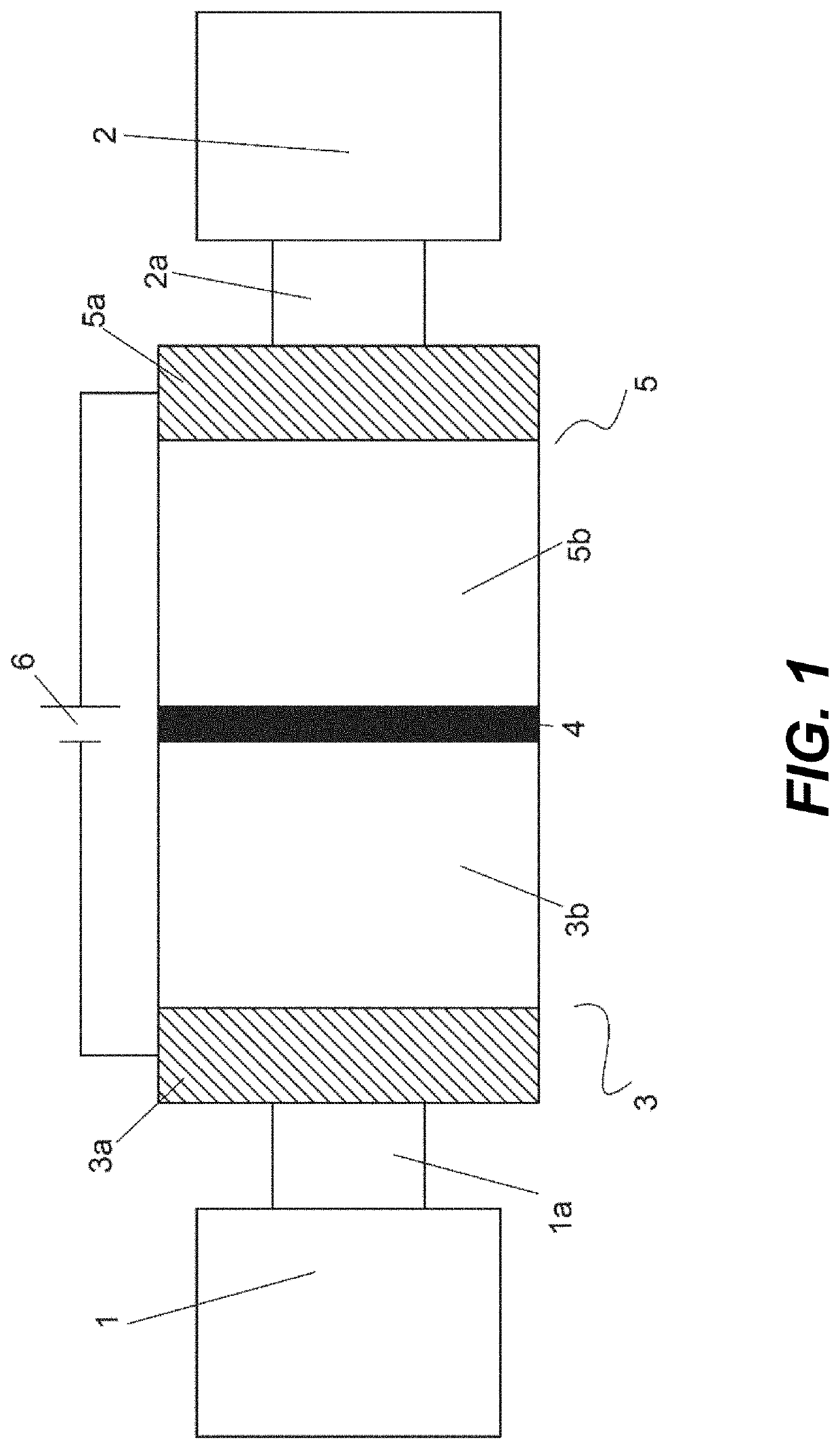
[0008]It is an object of the invention to provide an alkaline flow battery assembly to solve the technical problems of the prior art. More concretely, the cation-selective membranes (CSMs) currently used in alkaline flow batteries are expensive. Indeed, CSMs are the most expensive element in the electrochemical reactor and the major contributor to the cost of the stack model. In addition, the ionic conductivity of these cation-selective membranes in alkaline media is lower than that in acid media due to the larger size of the K+ and Na+, with respect to H+, limiting the maximum current density at which the electrochemical reactor can be operated. The operating current density has a tremendous impact in the cost of the stack as well; the lower the current density, the larger reactor area and the higher cost. The technical problem is solved by the assembly of claim 1. In the dependent claims it is disclosed other embodiments of the assembly.

[0009]The present invention is based on the ...


PUM

PropertyMeasurementUnit
current densitiesaaaaaaaaaa
operating temperatureaaaaaaaaaa

Abstract

An alkaline flow battery assembly comprising an electrochemical reactor including a positive compartment (5) and a negative compartment (3); wherein the positive compartment (5) comprises a positive electrode (5a) and houses catholyte (5b) whereas the negative compartment (3) comprises a negative electrode (3a) and houses anolyte (3b); wherein the negative compartment (3) is connected through a conduct (1a) in fluid communication to a first container (1) storing anolyte whereas the positive compartment (5) is connected through a conduct (2a) in fluid communication with a second container (2) storing catholyte; and wherein the anolyte and the catholyte are identical alkaline redox solutions comprising a first electro-active species A and a second electro-active species B, being the species A and B compatible between them; and wherein the negative compartment (3) and the positive compartment (5) are separated by means of a microporous separator (4).

Description

CROSS-REFERENCE TO RELATED APPLICATION[0001]This application is a national stage filing of PCT / ES2020 / 070277, filed on Apr. 29, 2020, having the same inventors and the same title, and which is incorporated herein by referenced in its entirety; which claims the benefit of priority from EP19382473.7, filed Jun. 6, 2019, having the same inventors and the same title, and which is incorporated herein by referenced in its entirety.[0002]The present invention relates to the field of batteries. More specifically, the present invention relates to the field of redox-flow batteries intended to decrease the cost of the electrochemical reactor of alkaline flow batteries while maintaining long cycle life.BACKGROUND OF THE INVENTION[0003]Energy storage technologies have become of vital importance for a variety of applications ranging from integration of intermittent renewable energy sources in the electrical grid to portable electronics. For stationary energy storage applications, redox flow batte...

Claims


Application Information

Patent Timeline
Patent Type & Authority Applications(United States)
IPC IPC(8): H01M8/04186H01M8/18
CPCH01M8/04186H01M2300/0014H01M8/188H01M8/1018Y02E60/50
Inventor ARBAIZAR, EDGAR VENTOSAANTOLÍN, DANIEL PÉREZRODRÍGUEZ, GUZMÁN GARCÍADEL VAL, JESÚS PALMA
Owner ENERGY STORAGE SOLUTIONS SL
Why Eureka
Try Eureka