Computer-implemented method for simulating a filling process of a mold cavity

a technology of mold cavity and computer implementation, which is applied in the field of computer implementation of methods, can solve the problems of complex calculations, time-consuming and laborious, and the inability to easily modify the die, and achieves the effect of requiring the performance of complex calculations and methods

Pending Publication Date: 2022-08-25
BASF AG
View PDF0 Cites 1 Cited by
  • Summary
  • Abstract
  • Description
  • Claims
  • Application Information

AI Technical Summary

Benefits of technology

The present invention provides methods, systems, programs, and databases for simulating the filling process of a mold in an injection molding process. Compared to existing methods, the present invention reduces processing time and requires less computation and memory capacity. Additionally, the present invention requires less effort for preparing the simulation model. The cell coordinate system determined for each cell in the simulation process also reduces the time required for determining the fiber orientation tensor.

Problems solved by technology

Due to high costs for designing and configuring the die, the die cannot be easily modified if any problems occur during injection molding.
However, generally the performing of such methods is very time-consuming and complex.
In particular, such methods typically require the performance of complex calculations, e.g. numerical solving of complex systems of differential equations.
Thus, such methods in general require large storage and computation capacities.
Despite the advantages involved in recent injection molding process simulation methods, several technical challenges remain.
Thus, still, simulating the filling process may be very time-consuming and complex, and required computation capacities may still be excessively high.

Method used


Image

  • Computer-implemented method for simulating a filling process of a mold cavity
  • Computer-implemented method for simulating a filling process of a mold cavity
  • Computer-implemented method for simulating a filling process of a mold cavity

Examples


Embodiment Construction

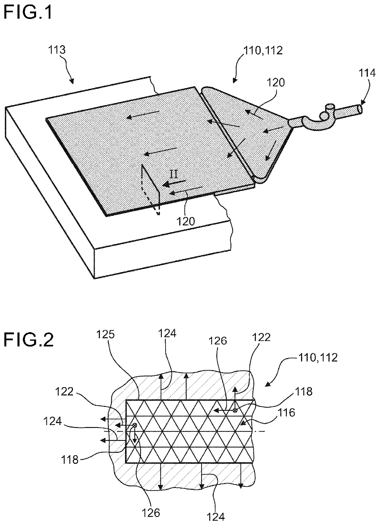
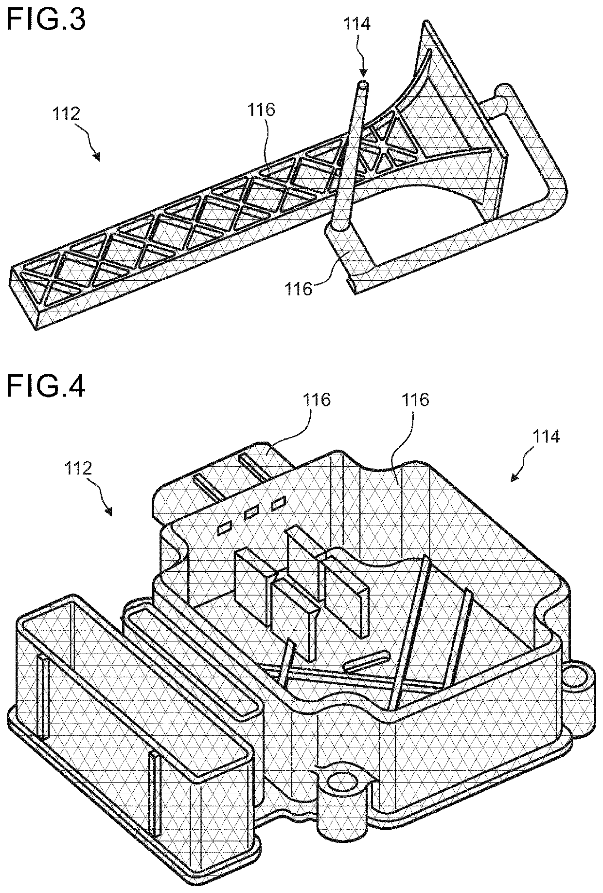
[0207]In FIG. 1 an embodiment of CAD data of an object 110 and a corresponding embodiment of a mold cavity 112 for injection molding the object is illustrated in a perspective view. For illustrational purposes a die 113 having a void in the shape of the mold cavity 112 is partly illustrated. A cavity injection point 114 may be defined on the mold cavity 112. FIG. 2 shows a section view of part of the mold cavity 112 as illustrated in FIG. 1. The mold cavity 112 may be discretized into a plurality of cells 116. Each cell 116 may comprise a cell coordinate system. The cell coordinate system may be defined by a first principal direction 118 parallel to a flow direction 120, as exemplarily illustrated in FIG. 1. Further, the cell coordinate system may be defined by a third principal direction 122 parallel to a surface normal direction 124, as exemplarily illustrated in FIG. 2, wherein the surface normal direction 124 may be oriented in a perpendicular fashion to the nearest cavity surfa...


PUM

PropertyMeasurementUnit
processing timeaaaaaaaaaa
lengthaaaaaaaaaa
lengthaaaaaaaaaa

Abstract

Described herein is a computer-implemented method for simulating a filling process of a mold cavity in an injection molding process using a plastic material, the method including: i) discretizing at least a part of the mold cavity into a plurality of cells; ii) defining a cavity injection point; iii) determining a surface normal direction perpendicular to the nearest cavity sur-face for each cell; iv) determining a cell coordinate system for each cell, defined by a first principal direction parallel to a flow direction, a third principal direction parallel to the normal direction, and a second principal direction perpendicular to the first and third principal directions; and v) determining the flow direction of a mold flow for each cell.

Description

TECHNICAL FIELD[0001]The invention relates to a computer-implemented method for simulating a filling process of a mold cavity in an injection molding process, a method for verifying a design of an object, a computer system, a computer program and a database for use in the computer-implemented method. Such methods, systems and devices can, in general, be employed for technical design or configuration purposes e.g. in a development phase of an injection molding process. However, further applications are possible.BACKGROUND ART[0002]Injection molding processes are common manufacturing processes in recent small and large scale manufacturing industry. In typical injection molding processes plastic material, such as thermoplastic, thermosetting or elastomer material, is melted, usually in a heating process, and then injected into an empty die, e.g. under an applied pressure. The plastic material is then hardened, usually in a cooling or curing process, in order to remain in the form given...

Claims


Application Information

Patent Timeline
Patent Type & Authority Applications(United States)
IPC IPC(8): B29C45/76B29C45/00B29C45/18
CPCB29C45/7693B29C45/0005B29C45/18B29C2945/76939B29K2995/005B29C45/76B29C45/26G06F30/20B29C70/06B29C2945/76973
Inventor GLASER, STEFANWONISCH, ANDREAS
Owner BASF AG
Why Eureka
Try Eureka