Electrode and Secondary Battery Including Same

a secondary battery and electrode technology, applied in the field of electrodes and secondary batteries, can solve the problems of high resistance of the battery, damage to the walled carbon nanotube unit, and difficulty in maintaining a conductive network in the active material layer of the electrode, so as to achieve the effect of improving energy density and life characteristics of the battery, conductive network, and maintaining a low resistance of the electrod

Pending Publication Date: 2022-09-08
LG ENERGY SOLUTION LTD
View PDF0 Cites 0 Cited by
  • Summary
  • Abstract
  • Description
  • Claims
  • Application Information

AI Technical Summary

Benefits of technology

[0013]An electrode according to the present invention includes a carbon nanotube structure in which 2 to 5,000 single-walled carbon nanotube units are bonded to each other, and thus a conductive network may be maintained smoothly even in the process of charging and discharging of a battery. Accordingly, resistance of the electrode may be maintained at a low level, energy density and life characteristics of the battery may be improved, and resistance of the battery may be reduced. In addition, since the carbon nanotube structure is present in the electrode in a long rope form, even though the battery is continuously charged and discharged, the decrease in conductivity due to the damage of the carbon nanotube structure can be suppressed, and a long conductive network can be formed. Moreover, since the point-type conductive agent included in the electrode contributes to the formation of a short conductive network, a conductive network may be evenly formed over the entire electrode due to using a combination of the point-type conductive agent and the carbon nanotube structure. Accordingly, life characteristics of the battery may be further improved, and a content of the conductive agent may be reduced to improve energy density of the battery and further reduce resistance of the battery. Furthermore, the point-type conductive agent may disperse, throughout the entire electrode, electrons in the electrode, and thus ignition due to a phenomenon in which electrons are localized to the carbon nanotube structure may be suppressed.

Problems solved by technology

Meanwhile, since conductivity of the electrode may not be secured only by the electrode active material such as a positive electrode active material or a negative electrode active material, resistance of the battery may be excessively high, and thus, the electrode typically additionally includes a conductive agent.
However, when charge and discharge of the battery are repeated, the surface of the single-walled carbon nanotube unit is damaged or the single-walled carbon nanotube unit is broken (finally a length of 1-3 μm), and thus, there is a limitation in that it is difficult to maintain a conductive network in the electrode active material layer.
Accordingly, the conductive network is blocked or reduced, and this degrades energy density and life characteristics of the battery and increases resistance of the battery.
However, the multi-walled carbon nanotubes are cut into an excessively short length during the preparation of dispersion due to the structure which is formed by growing in a node, and thus there is a limitation to improve the conductivity of the electrode.

Method used


Image

  • Electrode and Secondary Battery Including Same
  • Electrode and Secondary Battery Including Same
  • Electrode and Secondary Battery Including Same

Examples


preparation example 1

type Conductive Agent Dispersion

[0108]A carbon black (diameter: 50 nm) having a specific surface area of 240 m2 / g and hydrogenated nitrile butadiene rubbers (weight-average molecular weight: 260,000 g / mol) were mixed with N-methylpyrrolidone (NMP) that is a solvent to prepare a mixture having a solid content of 16.5 wt %.

[0109]The mixture was stirred in a bead-mill method, and bundle-type carbon nanotubes were dispersed in the solvent to prepare a conductive agent dispersion. In this case, the diameter of the beads was 1 mm, the revolution speed of the agitation container containing the beads was 3,000 RPM, and the stirring was performed for 60 minutes.

[0110]In the conductive agent dispersion, an amount of the carbon black was 15 wt %, and an amount of the hydrogenated nitrile butadiene rubbers was 1.5 wt %.

preparation example 2

Nanotube Structure Dispersion

[0111]Bundle-type single-walled carbon nanotubes (having a specific surface area of 650 m2 / g) composed of single-walled carbon nanotube units (having an average diameter of 1.5 nm) and polyvinylidene fluoride (PVdF, KF9700, weight-average molecular weight: 580,000 g / mol) were mixed in N-methyl pyrrolidone (NMP) that is a solvent to prepare a mixture so that a solid content was 2.4 wt %.

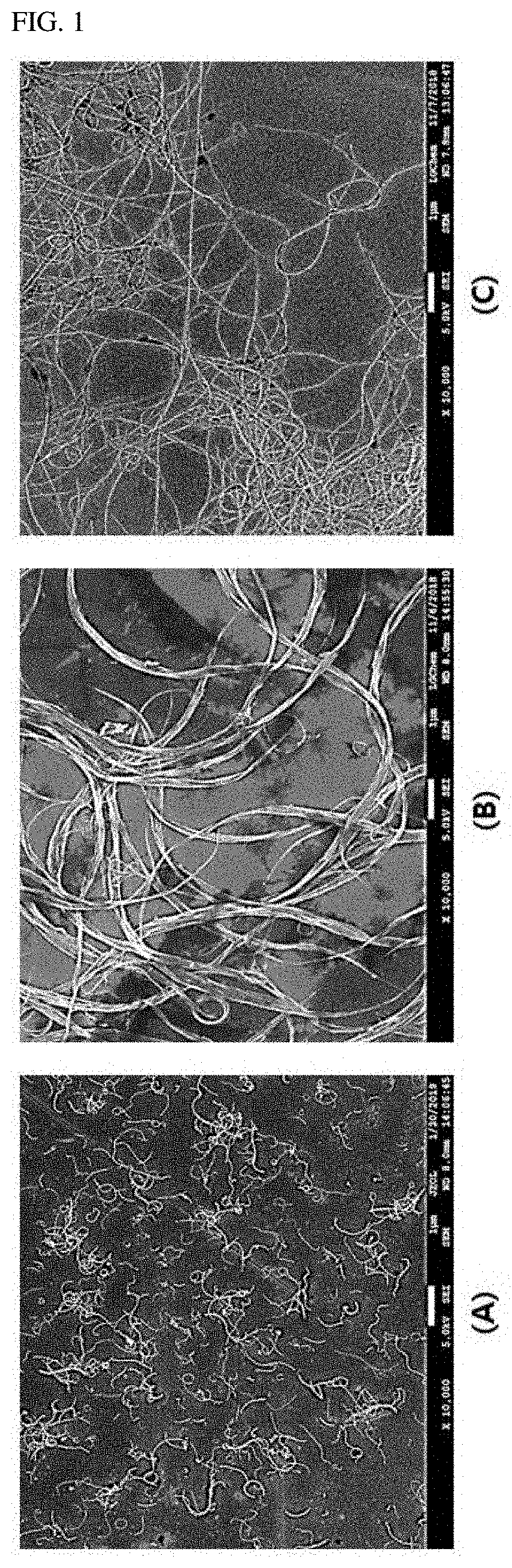
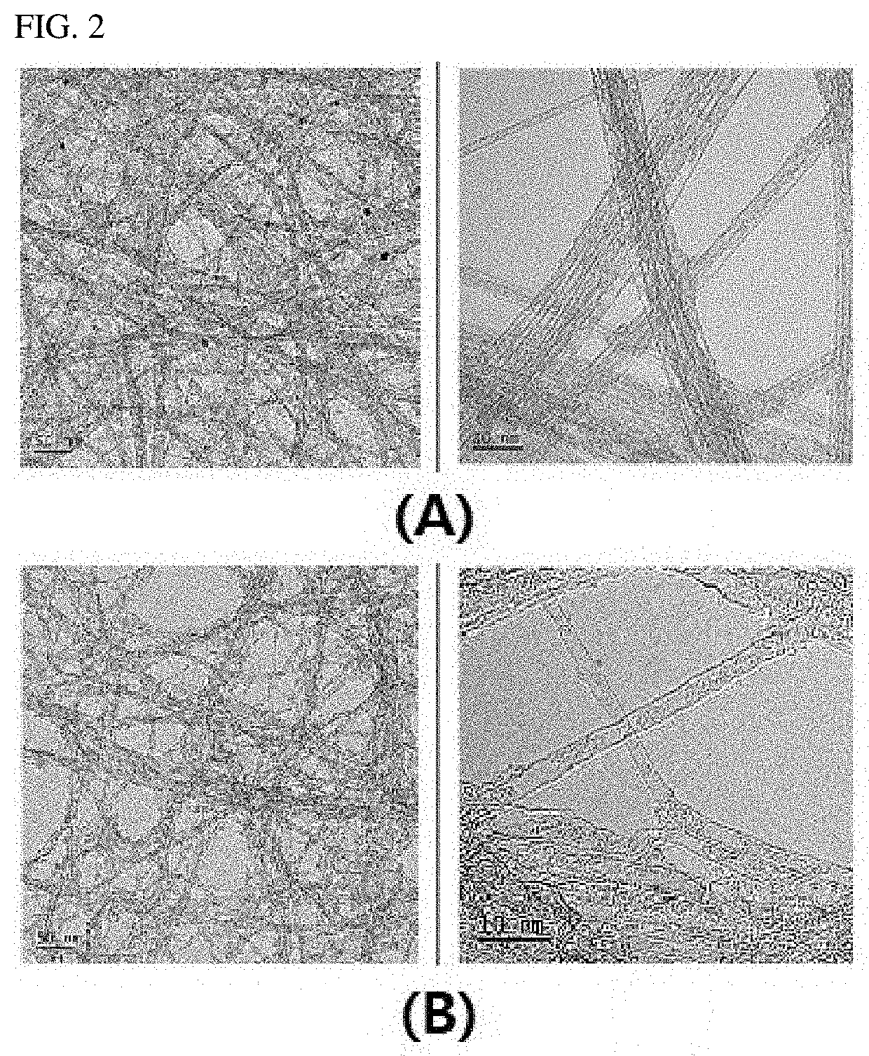
[0112]The mixture was stirred in a bead-mill method, and thus the bundle-type single-walled carbon nanotubes were dispersed in the solvent to prepare a carbon nanotube structure dispersion. In this case, the diameter of the beads was 1 mm, the revolution speed of the agitation container containing the beads was 3,000 RPM, and the stirring was performed for 60 minutes. The carbon nanotube structure dispersion included a carbon nanotube structure having a form in which 2 to 5,000 single-walled carbon nanotube units were bonded side by side (see (A) of FIG. 2).

[0113]In the ca...

preparation example 3

Nanotube Structure Dispersion

[0114]In Preparation Example 2, polyvinylidene fluoride having a weight-average molecular weight of 680,000 g / mol was used instead of the polyvinylidene fluoride having a weight-average molecular weight of 580,000 g / mol to prepare a carbon nanotube structure dispersion containing carbon nanotube structures having an average length of 20 μm.


PUM

PropertyMeasurementUnit
lengthaaaaaaaaaa
diameteraaaaaaaaaa
diameteraaaaaaaaaa

Abstract

An electrode includes an electrode active material layer, the electrode active material layer including an electrode active material and a conductive agent, the conductive agent including: a point-type conductive agent; and a carbon nanotube structure in which 2 to 5,000 single-walled carbon nanotube units are bonded to each other, wherein the carbon nanotube structure has an average length of 1 μm to 500 μm, and the carbon nanotube structure is contained in the electrode active material layer in an amount of 0.01 wt % to 5.0 wt %. A secondary battery including the electrode is also provided.

Description

TECHNICAL FIELDCross-Reference to Related Applications[0001]This application claims the benefit of the priority of Korean Patent Application No. 10-2019-0123301, filed on Oct. 4, 2019, the disclosure of which is incorporated herein in its entirety by reference.Technical Field[0002]The present invention relates to an electrode and a secondary battery including the same, the electrode including an electrode active material layer, the electrode active material layer including an electrode active material and a conductive agent, the conductive agent including: a point-type conductive agent; and a carbon nanotube structure in which 2 to 5,000 single-walled carbon nanotube units are bonded to each other, wherein the carbon nanotube structure has an average length of 1 μm to 500 μm, and the carbon nanotube structure is contained in the electrode active material layer in an amount of 0.01 wt % to 5.0 wt %.BACKGROUND ART[0003]Demand for batteries as an energy source has been significantly in...

Claims


Application Information

Patent Timeline
Patent Type & Authority Applications(United States)
IPC IPC(8): H01M4/62
CPCH01M4/625H01M2004/021H01M4/13H01M10/052B82Y30/00H01M4/131H01M2004/028
Inventor YUN, HYUN WOONGKIM, YONG JUNCHOI, SOON HYUNGKIM, TAE GONHAH, HOE JIN
Owner LG ENERGY SOLUTION LTD
Why Eureka
Try Eureka