Method of manufacturing solid electrolyte sheet, and solid electrolyte sheet

Pending Publication Date: 2022-09-29
HONDA MOTOR CO LTD
0 Cites 0 Cited by

AI-Extracted Technical Summary

Problems solved by technology

However, conventional manufacture of solid electrolyte layers has the following problems.
Besides, since the support exists near the bonding surface, the insertion and desorption of lithium ions is ...

Benefits of technology

[0015]According to the present invention, provided is a method of manufacturing a solid electrolyte sheet, and a solid electrolyte sheet that can improve battery output performance by smoothly inserting and desorbing lithium ions from a soli...

Abstract

Provided is a method of manufacturing a solid electrolyte sheet, and a solid electrolyte sheet that can improve battery output performance, and can suppress interfacial peeling and short-circuiting between the solid electrolyte layer and the electrode layer. A method of manufacturing a solid electrolyte sheet includes: a first step of a base with coating slurry containing a solid electrolyte; a second step of drying the slurry on the base to form a solid electrolyte layer; a third step of stacking a sheet-like three-dimensional structure on the top surface of the solid electrolyte layer; a fourth step of coating the inside and top of the three-dimensional structure with slurry containing a solid electrolyte; and a fifth step of drying the slurry coated on the inside and on the top of the three-dimensional structure to obtain a solid electrolyte sheet filled with the solid electrolyte.

Application Domain

Technology Topic

Image

  • Method of manufacturing solid electrolyte sheet, and solid electrolyte sheet
  • Method of manufacturing solid electrolyte sheet, and solid electrolyte sheet
  • Method of manufacturing solid electrolyte sheet, and solid electrolyte sheet

Examples

  • Experimental program(1)

Example

Example
Preparation of Solid Electrolyte Sheet
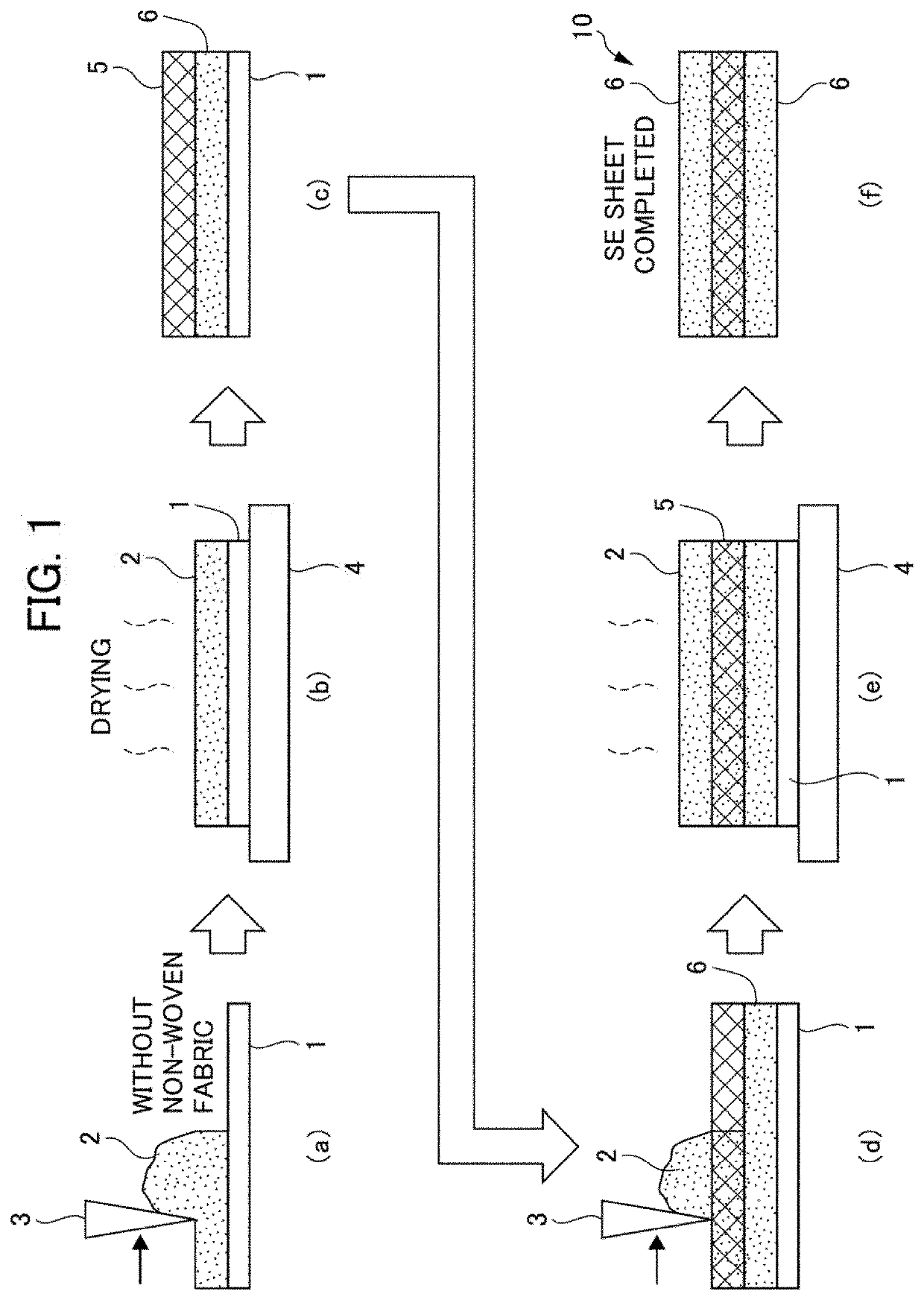
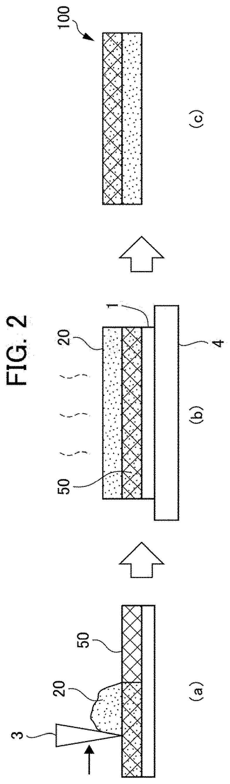
[0054]Slurry of a solid electrolyte was prepared by mixing the solid electrolyte with a solvent. A solid electrolyte layer was formed on the base by coating a removable base with slurry of the solid electrolyte and then drying it on a hot plate. Next, a non-woven fabric as a three-dimensional structure was placed on the top surface of the solid electrolyte layer, and the slurry of the solid electrolyte was applied again from the top of the three-dimensional structure. The work was then dried on the hot plate again and pressed after the base was removed, thereby yielding the solid electrolyte sheet according to the example. A plurality of solid electrolyte sheets of the example were prepared with different coating thicknesses of the solid electrolyte slurry, and used for the following evaluation tests.
Fabrication of Solid-State Battery
[0055]A solid-state battery for evaluation was prepared by stacking a positive electrode layer containing NCM as a positive electrode active material, the aforementioned solid electrolyte sheet, and a negative electrode layer containing graphite as a negative electrode active material in this order, and then pressing the work. The following evaluation tests were conducted using the solid-state battery for evaluation.
Comparative Example
[0056]The non-woven fabric as a three-dimensional structure that was used in the example was placed on a removable base, and slurry containing the solid electrolyte prepared in the same way as in Example 1 was coated from top of the non-woven fabric. Subsequently, the work was dried on a hot plate, and the removable base was then removed and the work was pressed to yield a solid electrolyte sheet according to the comparative example. Using the resulting solid electrolyte sheet, a solid-state battery for evaluation was fabricated through the same procedure as in the example. Multiple solid electrolyte sheets of the comparative example were also prepared with different coating thicknesses of the solid electrolyte slurry, and used for the following evaluation tests.
Cross-Sectional SEM Observation
[0057]The obtained solid electrolyte sheets of the example and comparative examples were subjected to cross-sectional SEM observation. FIG. 4 shows a cross-sectional SEM image of the solid electrolyte sheet according to the example. As shown in FIG. 4, regarding the solid electrolyte sheet according to the example, it was confirmed that the non-woven fabric as a three-dimensional structure was located approximately in its center defined with respect to the thickness direction. FIG. 5 shows a cross-sectional SEM image of the solid electrolyte sheet according to the comparative example. As shown in FIG. 5, regarding the solid electrolyte sheet according to the comparative example, it was confirmed that the non-woven fabric as a three-dimensional structure was located near one side.
DC Resistance Measurement Test
[0058]The evaluation batteries obtained above were subjected to a DC resistance measurement test. The batteries were discharged with a constant current at 50% SOC and the DC resistance was measured at 10 seconds. The results are shown in FIG. 6.
[0059]FIG. 6 shows the relationship between the post-pressing thickness and the DC resistance of each solid electrolyte (SE) sheet in the example and comparative examples. The vertical axis in FIG. 6 indicates each measured value as a relative value where the maximum DC resistance obtained in this test is 1. As shown in FIG. 6, it was confirmed that the solid-state battery using the solid electrolyte sheet according to the example had lower DC resistance than the solid-state batteries using the solid electrolyte sheets according to the comparative examples, regardless of the thickness of each solid electrolyte sheet. The results revealed that the output performance of the battery with the solid electrolyte sheet of the example was improved in compared to that with the solid electrolyte sheets of the comparative examples.
Evaluation Test of Short-Circuit Deterrent Effect
[0060]The evaluation batteries obtained above were subjected to a short circuit effect prevention evaluation test. After each evaluation battery was left for 10 days with no current flowing through it at a charge rate (SOC) of 20%, the open circuit voltage was measured. When the voltage between the positive and negative terminals of the solid-state battery was 0.000 V, the battery was determined to have a short circuit. The results are shown in FIG. 7.
[0061]FIG. 7 shows the relationship between the post-pressing thickness and the battery capacity of each solid electrolyte (SE) sheet in the example and comparative example. The vertical axis in FIG. 7 indicates each measured value as a relative value where the maximum battery capacity obtained in this test is 1. As shown in FIG. 7, it was confirmed that the solid-state battery using the solid electrolyte sheet according to the comparative example short-circuited when the solid electrolyte layer was thinner. In contrast, it was confirmed that solid-state battery using the solid electrolyte sheet according to the example could be a solid-state battery having a high battery capacity without short-circuiting, regardless of the thickness of the solid electrolyte sheet.
EXPLANATION OF REFERENCE NUMERALS
[0062] 1 Base [0063] 2, 20 Slurry of solid electrolyte [0064] 3 Blade [0065] 4 Dryer [0066] 5, 50 Three-dimensional structure [0067] 6 Solid electrolyte layer [0068] 10 Solid Electrolyte Sheet

PUM

no PUM

Description & Claims & Application Information

We can also present the details of the Description, Claims and Application information to help users get a comprehensive understanding of the technical details of the patent, such as background art, summary of invention, brief description of drawings, description of embodiments, and other original content. On the other hand, users can also determine the specific scope of protection of the technology through the list of claims; as well as understand the changes in the life cycle of the technology with the presentation of the patent timeline. Login to view more.

Similar technology patents

Alternator with front end accessory drive

ActiveUS20170257017A1Decreasing vehicle fuel efficiencyImprove output performanceDynamo-electric gearsMechanical energy handlingDynamoEngineering
Owner:FORD GLOBAL TECH LLC

Classification and recommendation of technical efficacy words

Why Eureka
Try Eureka