Receptacle for holding an active substance and corresponding cap and container

a technology for storing containers and active substances, which is applied in the field of storing containers, can solve the problems of contaminating goods contained therein, weak mechanical connection between the canister body and the cap, and sometimes problematic mechanical assembly of the canisters

Pending Publication Date: 2022-10-06
AIRNOV INC
View PDF0 Cites 1 Cited by
  • Summary
  • Abstract
  • Description
  • Claims
  • Application Information

AI Technical Summary

Problems solved by technology

Mechanically assembled canisters are sometimes problematic in that the mechanical connection between the canister body and the cap might not be strong enough to withhold a deformation of the canister under load conditions.
Such load conditions might occur during use in a container filled with particulate matter or under exceptional circumstances, e.g. when the container is inadvertently dropped onto a hard surface.
The resulting undesired opening of the canister upon deformation has the consequence that its contents, e.g. dehydrating agents or oxygen adsorbents, might be introduced into the interior of the container and might contaminate goods contained therein, like drugs.
However, the welding or any other comparable heat treatment to a porous membrane might be problematic because either the welded connection is weak or the membrane might be more sensitive to heat than the canister body.
Accordingly, a heat treatment of a porous membrane might negatively influence its density, i.e. its permeability, and its behavior at the welded seams due to the degradation of the material of the membrane under an excessive thermal load.
As a further problem, the functional material inside the canister migh

Method used


Image

  • Receptacle for holding an active substance and corresponding cap and container
  • Receptacle for holding an active substance and corresponding cap and container
  • Receptacle for holding an active substance and corresponding cap and container

Examples


second embodiment

[0091]Turning now to the second embodiment as shown in FIGS. 6 to 10, the overall structure is quite similar to that as described in the embodiment according to FIGS. 1 to 5. Therefore, the description of many elements also denoted in one of FIGS. 6 to 10 can be omitted with reference to the previous explanations.

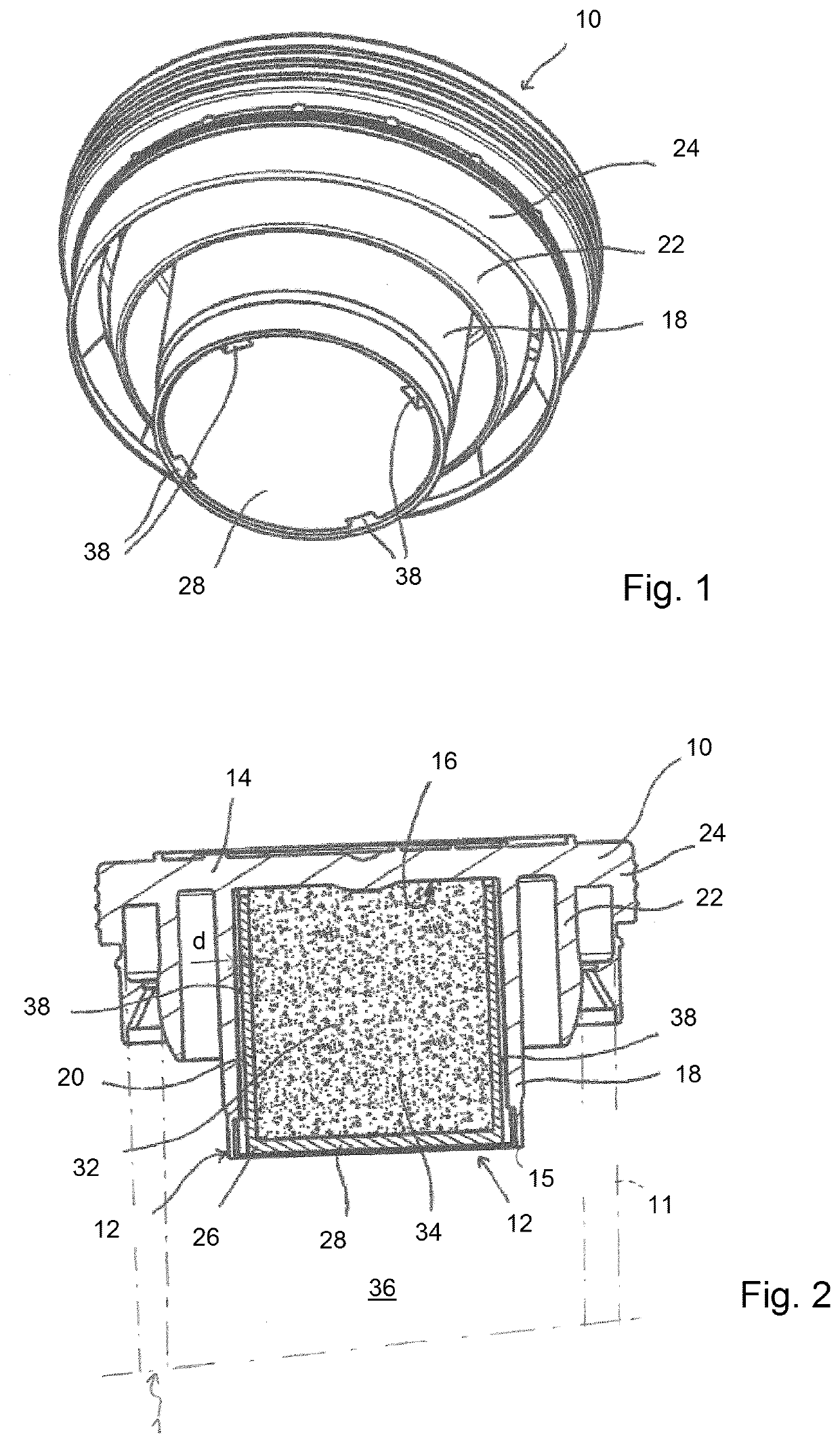
[0092]As can be seen in FIGS. 6 and 7, the second element 26 of the receptacle 12 is arranged relative to the first element 30 such that the radial arrangement of the skirt 18 and the sheath 20 is reversed. As can be best seen in FIG. 7, the sheath 20 is arranged radially outwards and concentrically to the skirt 18. The sheath 20 is dimensioned such that it tightly fits over the outer circumferential surface of the skirt 18 so that it is frictionally held at the abutting regions 21, once the receptacle 12 has been mounted by combining the first and second elements.

[0093]The chamber 32 is formed between the first main side 16 of the transverse wall 14, the skirt 18 and the b...

third embodiment

[0099]FIG. 11 shows a receptacle which is very similar to that according to FIG. 7. The major difference to the embodiment of FIG. 7 lies in the fact that the first element 30 of the receptacle 12 according to FIG. 11 is not integrally formed with a cap. Instead, the first element 30 and the second element 26 form a receptacle which is a separate canister and which can be attached to the base of a cap, preferably by means of a snap-fit connection.

[0100]In the fourth embodiment shown in FIGS. 12 to 16, elements that are similar to those of the previous embodiments have the same references. In the fourth embodiment, the receptacle 12 according to the invention is integrated in a bottom part 50 of the body 11 of a container 1 for storing sensitive products. The bottom part 50 of the container body 11 has a transverse base wall 54 with a first main side 56 facing the interior of the container 1.

[0101]The transverse wall 54 is integrally provided with the circular side wall 58 of the con...

fourth embodiment

[0102]The second element 26 is dimensioned so that, in the assembled configuration of the receptacle 12, it is frictionally held, preferably tightly held by means of a press-fit at the abutting regions 21 between the sheath 20 and the side wall 58, within the side wall 58 of the first element 50. In this fourth embodiment, the chamber 32 which contains an active substance 34 is delimited by the first main side 56 of the transverse wall 54, the sheath 20 and the bottom wall 28.

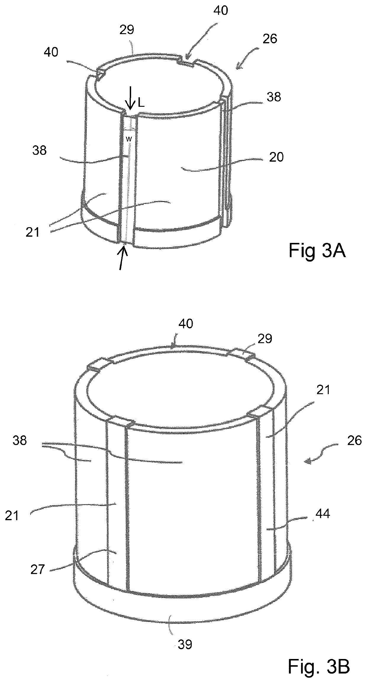
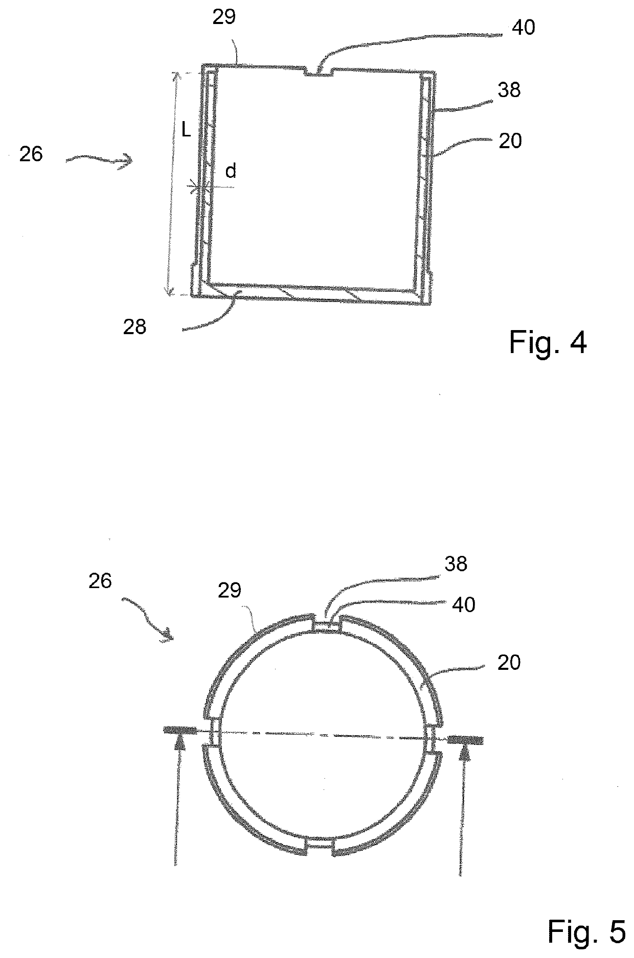
[0103]In order to allow the exchange of air between the chamber 32 and the atmosphere in the container 1, a ventilation path with ventilation grooves 38 is provided. The ventilation grooves 38 are formed, as can be best seen in FIG. 16, in the outer circumferential surface of the sheath 20, so that in the assembled state of the first element 50 and the second element 26, the ventilation grooves 38 are formed between the inner circumferential surface of the side wall 58 and the outer circumferential surface of t...


PUM


Abstract

A receptacle is designed for a chamber for an active substance. The receptacle includes two main elements. A first element is a transverse wall with a first main side facing an interior of the chamber, and a peripheral wall formed with the first main side of the transverse wall. A second element includes a bottom wall and a sheath extending from the bottom wall. The peripheral wall and the sheath surround one another and are in contact with each other so that the chamber is formed between the bottom wall, the transverse wall, the peripheral wall and/or the sheath. At least one ventilation groove is provided between the peripheral wall and the sheath form a ventilation channel connecting the chamber with the outside atmosphere.

Description

FIELD OF THE INVENTION[0001]The invention relates to a receptacle intended to regulate the atmosphere in a container for storing sensitive products, the receptacle being designed to be at least partially filled with an active substance and permit gases and vapors to enter the receptacle for interacting with the active substance. The invention also relates to a cap for closing an open end of a container body and comprising such a receptacle, to a container body comprising such a receptacle, and to a container for storing loose products as well as its use.BACKGROUND OF THE INVENTION[0002]A number of small desiccant canisters have been disclosed, which are formed from gas and liquid impermeable body portions which can be perforated and onto which are secured one or more perforated end caps. These canisters generally contain a desiccant material which adsorbs moisture from the air as the air flows through the perforations provided in an end cap of the desiccant canister.[0003]Such canis...

Claims


Application Information

Patent Timeline
IPC IPC(8): A61J1/14A61J1/20B65D81/26B65D55/16
CPCA61J1/1425A61J1/2072B65D81/268B65D55/16B65D51/244B01L3/50825B01L3/523B01L2200/023B01L2200/0689B01L2200/12B01L2300/042B01L2300/048A61J9/008A61J1/2075A61J1/2065B65D51/24B01D2257/80B01D2257/90B01D2257/104B01D53/0407B65D51/28
Inventor LEBON, JACQUY
Owner AIRNOV INC
Why Eureka
Try Eureka