
Beam spot tuning in a radiation therapy system

Pending Publication Date: 2022-10-06
VARIAN MEDICAL SYSTEMS
View PDF2 Cites 0 Cited by
  • Summary
  • Abstract
  • Description
  • Claims
  • Application Information

AI Technical Summary

Benefits of technology

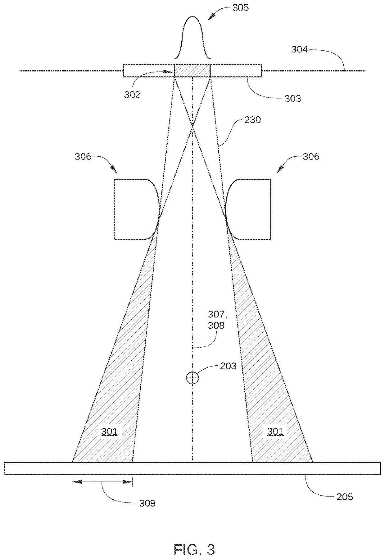
The patent text describes a computer-implemented procedure that allows for the direct measurement and modification of beam spot size, shape, and intensity distribution in a radiation therapy system using an existing imaging panel. This allows for the prevention of asymmetric beam spots or beams that do not meet the necessary geometrical requirements. The procedure can be used as part of factory setup, an on-site quality-assurance tool, or a periodic service tool to confirm the radiation target energy density per unit beam area is within acceptable limits and to ensure reliable target power levels and extended target life for the radiation therapy system.

Problems solved by technology

Unfortunately, direct measurement of the beam spot in a radiation therapy system can be difficult to implement.
As a result, fitting a planning target volume with a high, uniform dose while limiting the irradiation of neighboring healthy tissues can be difficult to achieve.
Conventional techniques for measuring properties of the beam spot of a radiation therapy system are time-consuming to set up and perform, rely on measuring equipment that is external to the radiation therapy system, and / or provide incomplete information about the beam spot.
However, a spot camera is a bulky piece of specialized equipment external to the radiation therapy system, requiring precise and time-consuming setup and training to be used.
However, this approach also involves the time-consuming setup and manual operation of equipment external to the radiation therapy system, greatly limiting where and how frequently this approach can be employed.
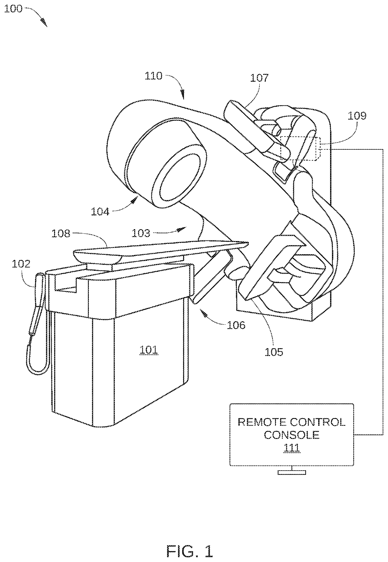
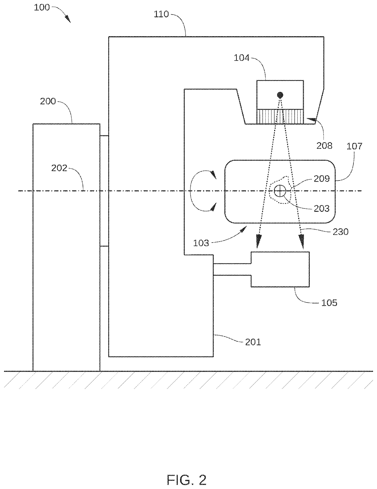
For radiation treatments that involve a high radiation dose and / or a small target size, such as stereotactic radiosurgery (SRS) and stereotactic radiotherapy (SRT), the required geometric accuracy of the delivery of treatment beam 230 can be adversely affected by the size, shape, location, and / or asymmetry of the treatment beam penumbra.
For example, in some embodiments, the radiation field fails to satisfy the predetermined radiation field quality specification when a total score associated with the radiation field does not meet or exceed a specified threshold value for the total score.

Method used


Image

  • Beam spot tuning in a radiation therapy system
  • Beam spot tuning in a radiation therapy system
  • Beam spot tuning in a radiation therapy system

Examples


Embodiment Construction

[0023]In the following detailed description, reference is made to the accompanying drawings, which form a part hereof. In the drawings, similar symbols typically identify similar components, unless context dictates otherwise. The illustrative embodiments described in the detailed description, drawings, and claims are not meant to be limiting. Other embodiments may be utilized, and other changes may be made, without departing from the spirit or scope of the subject matter presented here. It will be readily understood that the aspects of the disclosure, as generally described herein, and illustrated in the figures, can be arranged, substituted, combined, and designed in a wide variety of different configurations, all of which are explicitly contemplated and make part of this disclosure.

INTRODUCTION

[0024]As noted above, for radiation treatments that involve a high radiation dose and / or a small target size, high geometric accuracy of the delivered radiation treatment is required. Many f...


PUM


Abstract

An example computer-implemented method for tuning a beam spot in a radiation therapy system has been disclosed. The example method includes configuring an electron beam to generate a first beam spot on an electron-beam target of the radiation therapy system, generating, using an imager of the radiation therapy system, a first plurality of projection images of the first beam spot, wherein each of the projection images of the first beam spot is generated with a line of sight blocked between the imager and a different respective portion of the beam spot, based on the first plurality of projection images, determining a value for one or more beam spot quality metrics associated with the first beam spot, and based on the value, determining whether the first beam spot is outside a specified quality range.

Description

CROSS-REFERENCE TO RELATED APPLICATION[0001]The present application is also related in subject matter to U.S. Patent Application No. ______ (Attorney Docket No. 2021-002U502), which is incorporated herein by reference.BACKGROUND[0002]Unless otherwise indicated herein, the approaches described in this section are not prior art to the claims in this application and are not admitted to be prior art by inclusion in this section.[0003]Radiation therapy is a localized treatment for a specific anatomical target (a planning target volume, or PTV), such as a cancerous tumor. Ideally, radiation therapy is performed on the planning target volume that spares the surrounding normal tissue from receiving doses above specified tolerances, thereby minimizing risk of damage to healthy tissue. Prior to the delivery of radiation therapy, an imaging system is typically employed to provide a three-dimensional image of the anatomical target and surrounding area. From such imaging, the size and mass of th...

Claims


Application Information

Patent Timeline
IPC IPC(8): A61N5/10
CPCA61N5/1043A61N5/1031A61N2005/1089A61N5/1075A61N2005/1054
Inventor CONSTANTIN, MAGDALENACASSESE, MARCELO
Owner VARIAN MEDICAL SYSTEMS
Learn More