Compression-molding method and device for permanent magnet

a permanent magnet and compression molding technology, which is applied in the direction of press rams, manufacturing tools, magnetic bodies, etc., can solve the problems of inability to further increase the intensity of the magnetic field of the electromagnet, the overall size of the compression device is large, and the structure is complicated. achieve the effect of increasing the orientation degree of the permanent magnet, increasing the magnetic field intensity, and high magnetic field

Active Publication Date: 2022-10-27
HUAZHONG UNIV OF SCI & TECH
View PDF1 Cites 0 Cited by
  • Summary
  • Abstract
  • Description
  • Claims
  • Application Information

AI Technical Summary

Benefits of technology

[0010]The beneficial effect of the invention is as follows. The method adopts the electromagnetic coil to generate the orientation magnetic field, and is able to generate the waveform and the magnitude of the magnetic field as required by adjusting, based on needs, the parameter of the current being passed into. Accordingly, the orientation magnetic field may be high, and the orientation degree of the permanent magnet can be increased. Meanwhile, the intensity of the magnetic field generated by the orientation coil may be determined by the current being passed into. Consequently, the issue that the magnetic field intensity cannot be further increased once saturation is reached no longer exists, and the magnetic properties of the permanent magnet formed through compression-molding can be improved. Besides, the magnetic powder is compressed by a compression tool driven by the electromagnetic force generated by the electromagnetic coil. Accordingly, a large compression force may be generated based on needs. As a result, the density of the permanent magnet is increased. Furthermore, by adopting the transient process, the time which the entire compression-molding process takes is short, and the power consumption is low. As a result, the cost can be reduced. Therefore, the method improves the properties of the permanent magnet formed by compression-molding, and solves the issue that the size of the electromagnet tends to be large and the issue that the orientation magnetic field intensity cannot be further increased in the conventional compression-molding technologies for permanent magnets. Thus, the method meets the practical demands gradually increasing in the industry.
[0011]On the basis of the above technical solution, the following modifications may also be made to the invention.
[0012]Additionally, the drive coil includes two drive coil sets. In a compression process, transient currents passed into the two drive coil sets are in opposite directions, so that an electromagnetic repulsive force is generated between the two drive coil sets. The repulsive force drives one of the drive coil sets to drive the compression tool to apply the molding compression force to the magnetic powder under compression.
[0013]The additional beneficial effect of the invention is that, in the compression process, the directions of the transient currents passed into the two drive coil sets are opposite, and when the two drive coil sets are close to each other, a great electromagnetic repulsive force is generated, and the compression tool is driven to apply the molding compression force to the magnetic powder under compression. In addition, the transient current passed into the orientation coil may be in the same direction with the transient current passed into one of the drive coils driving the compression tool. Accordingly, an attractive force is generated therebetween, and the molding compression force applied to the magnetic powder under compression is further increased. Accordingly, the method is highly flexible and exhibits high compression efficiency.
[0014]Preferably, the drive coil is a drive coil set. In a compression process, the transient currents synchronously passed into the drive coil set and the orientation coil are in a same direction. An electromagnetic attractive force is generated between the drive coil and the orientation coil. The attractive force drives the drive coil set to drive the compression tool to apply the molding compression force to the magnetic powder under compression.
[0015]The additional beneficial effect of the invention is that, in the compression process, the compression-molding of the magnetic powder under compression is realized by using only one drive coil set. Accordingly, the size of the compression structure is significantly reduced.

Problems solved by technology

If the magnetic powder is not subjected to an orientation magnetic field during the compression process, the magnetic powder may form an isotropic bonded permanent magnet with less favorable magnetic properties after compression-molding.
As a result, the compression device may have a large overall size, a complicated structure, and require a high cost.
Moreover, once saturated, the intensity of the magnetic field of the electromagnet cannot be further increased.
As a result, the magnetic properties of the permanent magnet are limited.
Furthermore, by adopting the transient process, the time which the entire compression-molding process takes is short, and the power consumption is low.
Additionally, the repulsive force drives the drive plate to drive the compression tool to apply the molding compression force to the magnetic powder under compression.
Additionally, the repulsive force drives the drive coil set to drive the compression tool to apply the molding compression force to the magnetic powder under compression.

Method used


Image

  • Compression-molding method and device for permanent magnet
  • Compression-molding method and device for permanent magnet
  • Compression-molding method and device for permanent magnet

Examples


embodiment 1

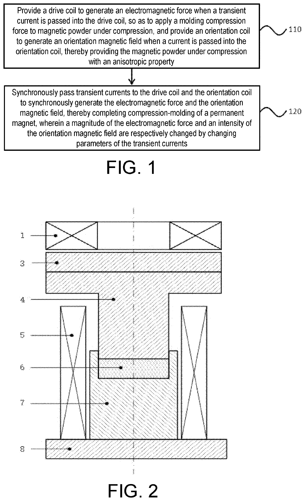
[0038]A compression-molding method 100 for a permanent magnet, as shown in FIG. 1, includes:

[0039]Step 110: providing a drive coil to generate an electromagnetic force when a transient current is passed into the drive coil, so as to apply a molding compression force to magnetic powder under compression; and providing an orientation coil to generate an orientation magnetic field when a current is passed into the orientation coil, thereby providing the magnetic powder under compression with an anisotropic property; and

[0040]Step 120: synchronously passing transient currents to the drive coil and the orientation coil to synchronously generate an electromagnetic force and the orientation magnetic field, thereby completing compression-molding of a permanent magnet, wherein a magnitude of the electromagnetic force and an intensity of the orientation magnetic field are respectively changed by changing parameters of the transient currents.

[0041]The orientation magnetic field and the electro...

embodiment 2

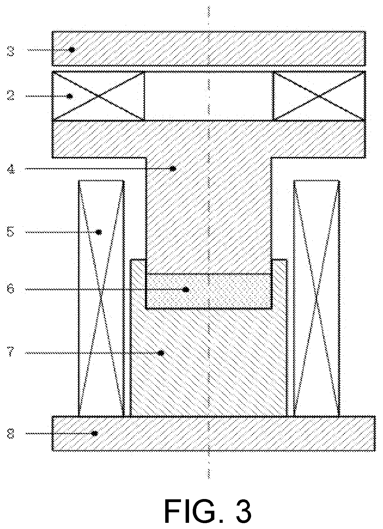
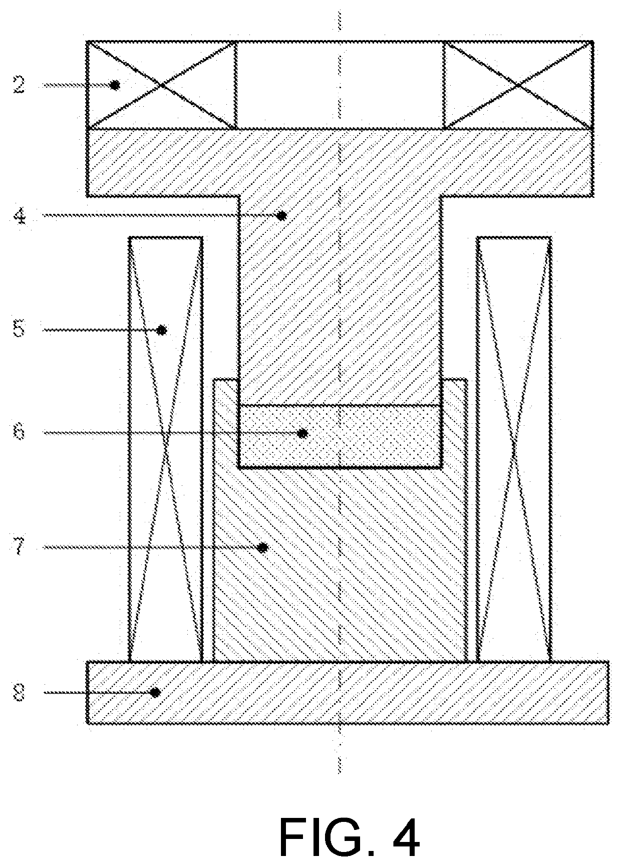
[0057]A compression-molding device for a permanent magnet includes a drive module, a compression tool, a mold, and an orientation coil. A groove to be filled with the magnetic powder under compression is provided at the center of the mold. The bottom of the compression tool contacts the magnetic powder under compression, the top of the compression tool contacts an end of the drive module, and the compression tool coincides with a central axis of the groove. The drive module generates the electromagnetic force as described in the compression-molding method for the permanent magnet according to Embodiment 1 above to drive the compression tool to apply the molding compression force to the magnetic powder under compression. The orientation coil is sleeved on the outer periphery of the mold to generate the orientation magnetic field as described in the compression-molding method for the permanent magnet according to Embodiment 1 above.

[0058]The drive module includes: two drive coils, one...


PUM

PropertyMeasurementUnit
magnetic fieldaaaaaaaaaa
anisotropic propertyaaaaaaaaaa
repulsive forceaaaaaaaaaa

Abstract

A compression-molding method for a permanent includes: providing a drive coil to generate an electromagnetic force when a transient current is passed into the drive coil, so as to apply a molding compression force to magnetic powder under compression, and providing an orientation coil to generate an orientation magnetic field when a transient current is passed into the orientation coil, thereby providing the magnetic powder under compression with an anisotropic property; and synchronously passing the transient currents to the drive coil and the orientation coil to synchronously generate the electromagnetic force and the orientation magnetic field, thereby completing compression-molding of the permanent magnet, wherein a magnitude of the electromagnetic force and an intensity of the orientation magnetic field are respectively changed by changing peak values of the transient currents.

Description

BACKGROUNDTechnical Field[0001]The invention relates to compression-molding of a permanent magnet, and more particularly relates to a compression-molding method and device for a permanent magnet.Description of Related Art[0002]Currently, the industrial processes of manufacturing permanent magnets include sintering, bonding, casting, and thermal compression / deformation. Among these processes, the sintering process is applied most widely. Most sintered permanent magnets are anisotropic magnets. A sintered permanent magnet is formed by placing magnetic powder in a loose state in the mold cavity of a compression device, molding the magnetic powder under an externally applied orientation magnetic field and pressure, and performing a sintering process to form a sintered permanent magnet after subjecting the magnetic powder to orientation and compression-molding.[0003]A bonding process includes placing the mixture of magnetic powder and a binder in the mold cavity of a compression device t...

Claims


Application Information

Patent Timeline
Patent Type & Authority Applications(United States)
IPC IPC(8): H01F41/02B22F3/087B22F3/00
CPCH01F41/0266B22F3/087B22F3/003B22F2202/05H01F13/003H01F41/0273B22F2999/00B30B11/008C22C2202/02B22F3/02B22F2003/033B22F3/03B30B1/42
Inventor LI, LIANGLV, YILIANG
Owner HUAZHONG UNIV OF SCI & TECH
Why Eureka
Try Eureka