
Logic gate with neuron circuit

a logic gate and neuron technology, applied in logic circuits using specific components, biological neural network models, physical realisation, etc., to achieve the effect of reducing the circuit area in the integrated circuit and minimizing the consumption of power and heat dissipation

Pending Publication Date: 2022-11-10
TOBB EKONOMI VE TEKNOLOJI UNIVERSITESI
View PDF0 Cites 0 Cited by
  • Summary
  • Abstract
  • Description
  • Claims
  • Application Information

AI Technical Summary

Benefits of technology

The invention is a logic gate with a neuron circuit that can be used to replace AND, OR, and MAJORITY logic gates. The logic gate uses the neuron circuit to convert parallel signals into serial signals and determine a threshold value based on the input signals. This threshold value is adjustable and can be used to minimize power consumption and heat dissipation by reducing the circuit area in integrated circuits. The logic gate with the neuron circuit has flexible and adjustable characteristics, making it highly versatile for different logic operations.

Problems solved by technology

However, the most important problem of these systems is their slow operation and high-power consumption.
Neuron circuits can be designed in terms of software, but the processes are carried out slowly because too many algorithms are running.
The problems with superconductor-based artificial nerve cells are that the circuits do not operate reliably, Single Flux Quantum (SFQ) is not compatible with the digital circuits, and that they are relatively complex structures having large areas.
When it is carried out with semiconductors, the size of the neuron circuits is large and in this case they are unpractical.
On the other hand, the neuron circuits produced by the semiconductors consume too much power.
Since the neuron circuits consume too much power, the current transmission also slows down.
In this case, the semiconducting neuron circuits cannot keep up with the brain in terms of the processing power.
On the other hand, it is not possible in the state of the art to integrate the neuron circuits to each other and to work with the circuits that enable to produce the input.
Furthermore, the neuron circuits provided in the current art cannot operate compatibly with the other logic gates (AND / OR, etc.) and are unable to receive and process the signal generated by the standard gates.
The most important disadvantage of the current gates is their requirement to the synchronization signals.
One of this design's problems is that the time delays can be high depending on the synchronous working obligation (clock pulse input) and multi-layered structure.
On the other hand, the power consumption and heat dissipation increase in the circuit because many junctions are used during the use of the logic circuits in the integrated circuits.

Method used


Image

  • Logic gate with neuron circuit
  • Logic gate with neuron circuit

Examples


Embodiment Construction

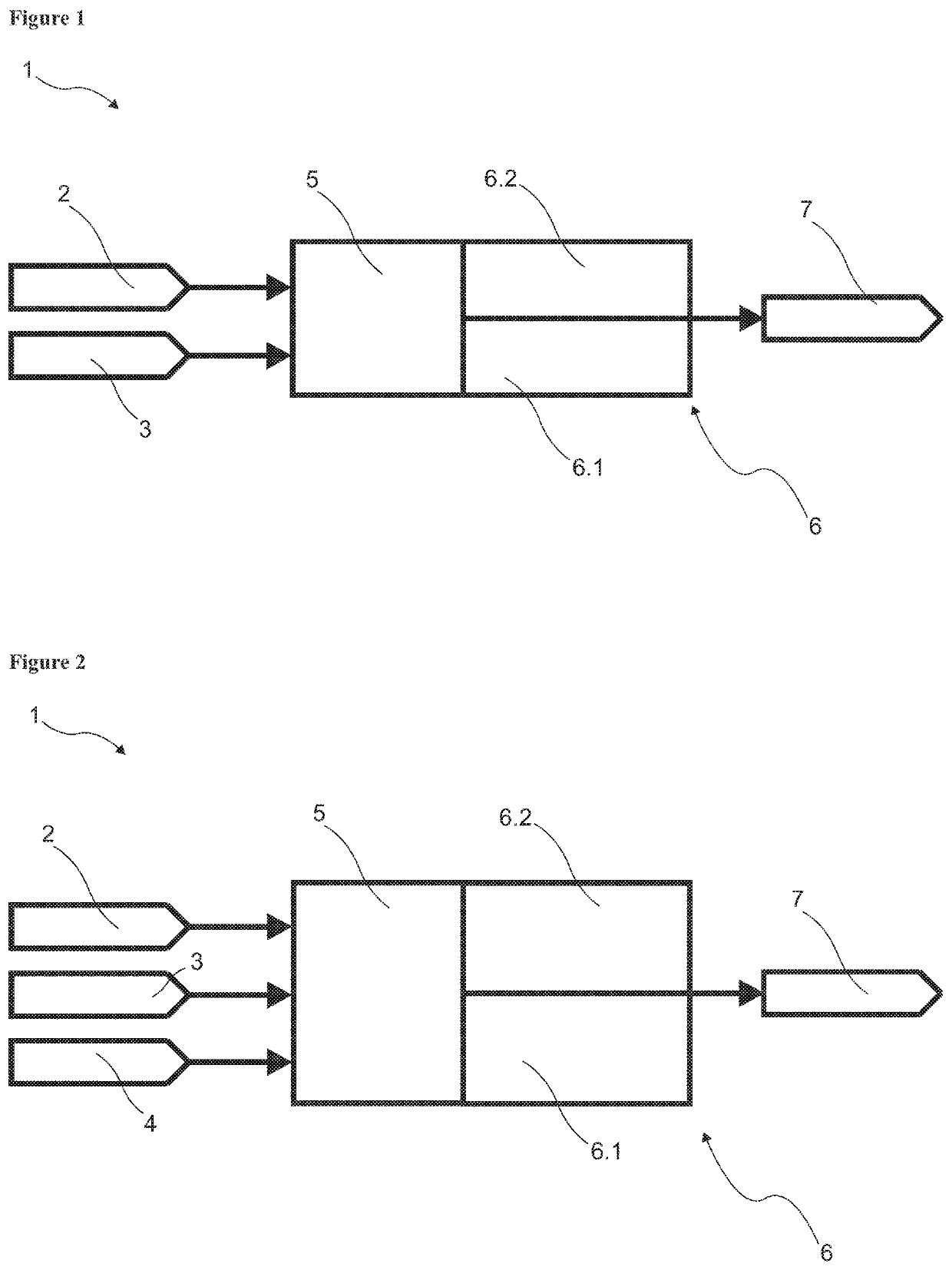
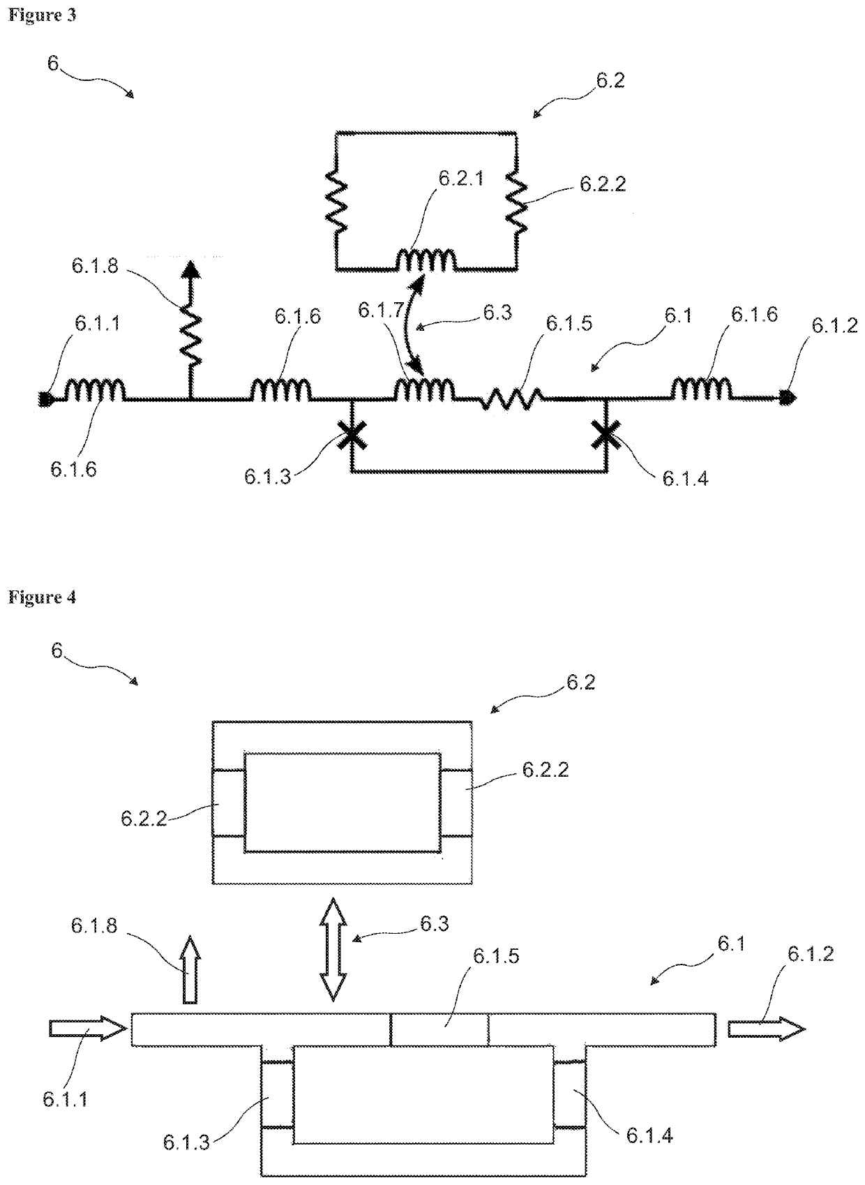
[0019]The logic gate with neuron circuit developed to fulfil the objects of the present invention is illustrated in the accompanying figures, in which:

[0020]FIG. 1. is a schematic view of the logic gate with neuron circuit which is used as AND and OR logic gate.

[0021]FIG. 2. is a schematic view of the logic gate with neuron circuit which is used as MAJORITY logic gate.

[0022]FIG. 3. is a schematic view of the neuron circuit.

[0023]FIG. 4. is a diagram view of the neuron circuit.

[0024]The parts in the figure are enumerated one by one and the parts correspond to these numbers are given in the following:

[0025]1. Logic gate with neuron circuit

[0026]2. First arithmetic input

[0027]3. Second arithmetic input

[0028]4. Third arithmetic input

[0029]5. Merger

[0030]6. Neuron circuit[0031]6.1. Threshold loop[0032]6.1.1. Input signal[0033]6.1.2. Output signal[0034]6.1.3. First junction[0035]6.1.4. Second junction[0036]6.1.5. Threshold resistance[0037]6.1.6. Threshold side inductor[0038]6.1.7. Thresho...


PUM


Abstract

A logic gate with a neuron circuit which is used in electronic logic circuits, enables the arithmetic inputs to give output signal over the threshold value depending on a set threshold value according to the used AND, OR and MAJORITY logic gates, and enables to realize the logic processes by adjusting the triggering threshold value.

Description

TECHNICAL FIELD[0001]The present invention relates to a logic gate with neuron circuit, which electronically applies the working principle of the neurons in human brain, compares collected input signals to a preferred threshold value, and enables to provide an output signal if the collected signal is above the threshold value.PRIOR ART[0002]Artificial Intelligence (AI) is the general name given to the modelling work of the systems that exhibit similar behaviours by getting inspired by the behavioural patterns of all of the living creatures in nature. AI is usually directed at analysing humans' thinking methods and developing artificial instructions similar to them. In general, AI implement the behaviours identified as intelligent when conducted by humans (intelligent behaviour) to be performed by machines. In other words, AI is a theory showing how the human mind works. It is aimed to make the machines more intelligent and useful by means of AI. AI enables the machines with a number...

Claims


Application Information

Patent Timeline
Patent Type & Authority Applications(United States)
IPC IPC(8): G06N3/063H03K19/195
CPCG06N3/063H03K19/195H03K19/1952
Inventor BOZBEY, ALIKARAMUFTUOGLU, ALTAY
Owner TOBB EKONOMI VE TEKNOLOJI UNIVERSITESI
Learn More