Zoom lens system

a zoom lens and lens body technology, applied in the field of zoom lens systems, can solve the problems of reducing the focus of the lens, unfavorable wide angle of field, and cost, and achieve the effect of reducing the cost and reducing the focus

Inactive Publication Date: 2000-01-18
OLYMPUS OPTICAL CO LTD
View PDF5 Cites 100 Cited by
  • Summary
  • Abstract
  • Description
  • Claims
  • Application Information

AI Technical Summary

Benefits of technology

JP-A-6- 194572, as already mentioned, shows that for zooming, the second and third lens groups move in opposite directions. However, a main portion of the zooming action is born by the second lens group while an auxiliary portion of the zooming action is born by the third lens group. The fourth lens group corrects for an image position in association with zooming, and has little, if any, zooming action. The fact that the second lens group has the zooming action means that zooming takes place by a change in the spacing between the first and second lens groups. For efficient zooming, it is thus required that the second lens group as well as the first lens group have strong refracting power. When the first lens group has strong refracting power, however, it is required that a negative lens be incorporated in the first lens group that has positive refracting power to correct for various aberrations, including chromatic aberration. In addition, the height of off-axis rays passing through the first lens group on the wide-angle side increases. This is unfavorable for making the angle of field wide.
According to each zoom lens system of the present invention, on the other hand, the third plus fourth lens groups move flatly or constantly from the image to object side along the wide-angle to telephoto end. That is, a main portion of the zooming action is born by the third and fourth lens groups. For this reason, the zooming action that is to be born by the second lens group is so reduced that the refracting power of the first lens group can be reduced. It is thus possible to construct the first lens group of one positive single lens and, at the same time, make the angle of field wide. When the first lens group has diminished refracting power, the occurrence of aberrations can be inhibited even with one positive lens, so that variations in chromatic aberration due to zooming can be corrected with no incorporation of a negative lens. In addition, the height of off-axis rays passing through the first lens group can be lowered, and this is favorable for making the angle of field wide.
To make a reasonable compromise between making the angle of field wide and simplifying the constructions of both lens and barrel arrangements, where a stop is located is of importance. When the angle of field is made wide, the location of the stop at a substantial center of the optical system is favorable for making the first and fourth lens groups compact. For this reason, the stop is located between the second and third lens groups. If, furthermore in this case, the stop is fixedly located on the optical axis, it is then possible to simplify the lens barrel arrangement.
To make each zoom lens system of the present invention wide in terms of the angle of field also means that the focal length of the overall zoom lens system is reduced relative to the size of an image pickup surface. Reducing the focal length of the overall zoom lens system causes the back focus thereof to be reduced, rendering it difficult to make sure of a space where members such as an optical filter are to be located. In the present invention, therefore, a sufficient back focus is ensured by diminishing the refracting power of the first lens group relative to that of the fourth lens group.
In each zoom lens system of the present invention, focusing may be achievable by the fourth lens group. However, the second lens group, too, is suitable for focusing, because the absolute value of the image-formation magnification of the second lens group is relatively small. Furthermore, the second lens group is located on the image side at the telephoto end with respect to the wide-angle end, so that a space sufficient to effect focusing by the second lens group is ensured on the telephoto side. By focusing with the second lens group in combination with the fourth lens group, it is thus possible to pick up images at shorter distances on the telephoto side in particular.
The lens groups may be positioned on the image side of the fourth lens group for the purpose of controlling the position of the exit pupil, making correction for aberrations, achieving compactness, etc.

Problems solved by technology

However, the system set forth in JP-A-6-94997 is disadvantageous in terms of cost because its lens barrel becomes large and heavy due to the first lens group that does not only have the largest outer diameter but is constructed of three lenses as well.
This is unfavorable for making the angle of field wide.
Reducing the focal length of the overall zoom lens system causes the back focus thereof to be reduced, rendering it difficult to make sure of a space where members such as an optical filter are to be located.
With the upper limit of 0.41 in this condition (2) exceeded, the height of off-axis rays passing through the first lens group increases, not only resulting in an increase in the diameter of the first lens group but also rendering it difficult to make sure of a sufficient back focus.
When the lower limit of 0.05 in condition (2) is not reached, not only does the efficiency of zooming at the second lens group become worse, but the overall length of the lens system increases as well.
Exceeding the upper limit of 0.2 results in an increase in the size of the first lens group, and is unfavorable for making sure of a back focus.
This is also unfavorable for making correction for negative distortion on the wide-angle side.

Method used


Image

  • Zoom lens system
  • Zoom lens system
  • Zoom lens system

Examples


Embodiment Construction

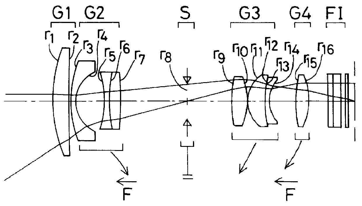
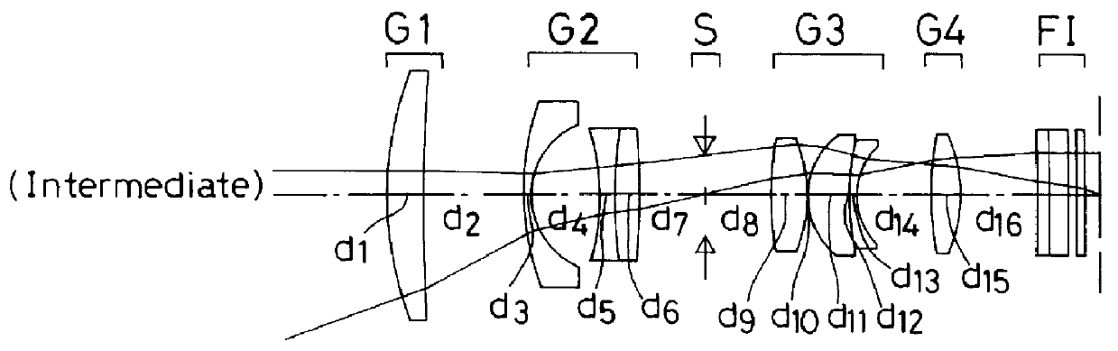
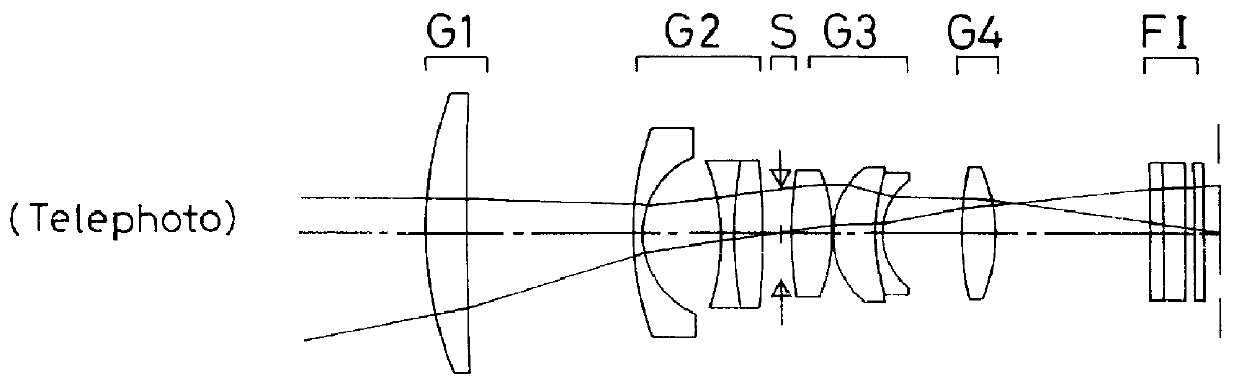
of the zoom lens system according to the present invention will now be explained specifically with reference to FIGS. 1A to 11L.

FIGS. 1A to 8C are sectional schematics of Examples 1-7, and 9 including the optical axes thereof. A lens arrangement of Example 8 is not shown because it is identical with that of Example 7. For the purpose of comparison, the positions of the respective lens groups at the wide-angle end, in an intermediate state, and at the telephoto end are illustrated together with an axial marginal ray and an off-axis principal ray. In the sectional schematics at the wide-angle end, arrows indicate the direction of movement of the respective lens groups for zooming from the wide-angle to telephoto end. Arrows with a capital F, given along the optical axis, show the respective lens groups upon being moved for focusing, and the direction of movement of the respective lens group. A capital S with a ground mark-indicates that the stop is fixed. A plane-parallel plate FI loc...


PUM


Abstract

The invention provides a zoom lens system which achieves a wide angle of field, has a simplified construction, and is suitable for use on video cameras. The zoom lens system comprises, in order from an object side thereof, a first lens group G1 having positive refracting power, a second lens group G2 having negative refracting power, a third lens group G3 having positive refracting power, and a fourth lens group G4 having positive refracting power. The second lens group G2 moves toward an image side thereof while the third G3 and fourth G4 lens groups move constantly toward the object side for zooming from a wide-angle end thereof to a telephoto end thereof. The first lens group G1 consists only of a positive single lens.

Description

1. Field of the InventionThe present invention relates generally to a zoom lens system, and more particularly to a wide-field-angle zoom lens system suitable for use on video cameras.2. Related ArtIn recent years, zoom lens systems of the type which, as typically disclosed in JP-A-63-29718, comprise four lens groups or positive, negative, positive, and positive lens groups as viewed from the object side, and in which zooming is carried out by the second group, and correction of an image position due to zooming, and focusing are performed by the fourth group, have prevailed for use on general-purpose video cameras. Most of these types of zoom lens systems are designed to have a field angle 2.omega. of about 50.degree. at the wide-angle end. JP-A-6-94997, on the other hand, discloses a four-group zoom lens system having a field angle as large as about 65.degree. at the wide-angle end. This zoom lens system, comprising positive, negative, positive, and positive lens groups from the obj...

Claims


Application Information

Patent Timeline
Patent Type & Authority Patents(United States)
IPC IPC(8): G02B15/163G02B15/173G02B15/20
CPCG02B15/173G02B15/144113
Inventor UZAWA, TSUTOMU
Owner OLYMPUS OPTICAL CO LTD
Why Eureka
Try Eureka