Stretch-forming machine with servo-controlled curving jaws

a servo-controlled, stretch-forming machine technology, applied in the direction of shaping safety devices, metal-working feeding devices, manufacturing tools, etc., can solve the problems of inconvenient mechanical adjustment, time-consuming mechanical adjustment, and risk to the ex-tent, so as to improve the safety of machine technicians and operators, and improve the effect of machine setup

Inactive Publication Date: 2000-02-01
CYRIL BATH
View PDF9 Cites 29 Cited by
  • Summary
  • Abstract
  • Description
  • Claims
  • Application Information

AI Technical Summary

Benefits of technology

It is another object of the invention to provide servo-control for the individual grippers which collectively form a curving jaw in order to provide quicker and more precise machine set-up.
It is another object of the invention to provide servo-control for the individual grippers which collectively form a curving jaw in order to provide a safer work environment for machine technicians and operators.
It is another object of the invention to provide servo-control for the individual grippers which collectively form a curving jaw in order to provide more efficient and precise metal forming.

Problems solved by technology

However, in prior art stretch-forming machines with curving jaws, the stroke of the hydraulic cylinder of each of the grippers is required to be mechanically adjusted and locked by a skilled set-up technicians.
Such mechanical adjustment is disadvantageous for several reasons.
First, manual, mechanical adjustment is time-consuming and subject to trial-and-error adjustment and re-adjustment.
Second, safety is compromised to the ex-tent that the technician is required to work in close proximity to heavy machinery and high hydraulic pressures.
Third, creeping maladjustment may occur during machine operation requiring down-time to correct.
Fourth, incorrect set-up may go unnoticed, resulting in wasted time and materials.

Method used


Image

  • Stretch-forming machine with servo-controlled curving jaws
  • Stretch-forming machine with servo-controlled curving jaws
  • Stretch-forming machine with servo-controlled curving jaws

Examples


Embodiment Construction

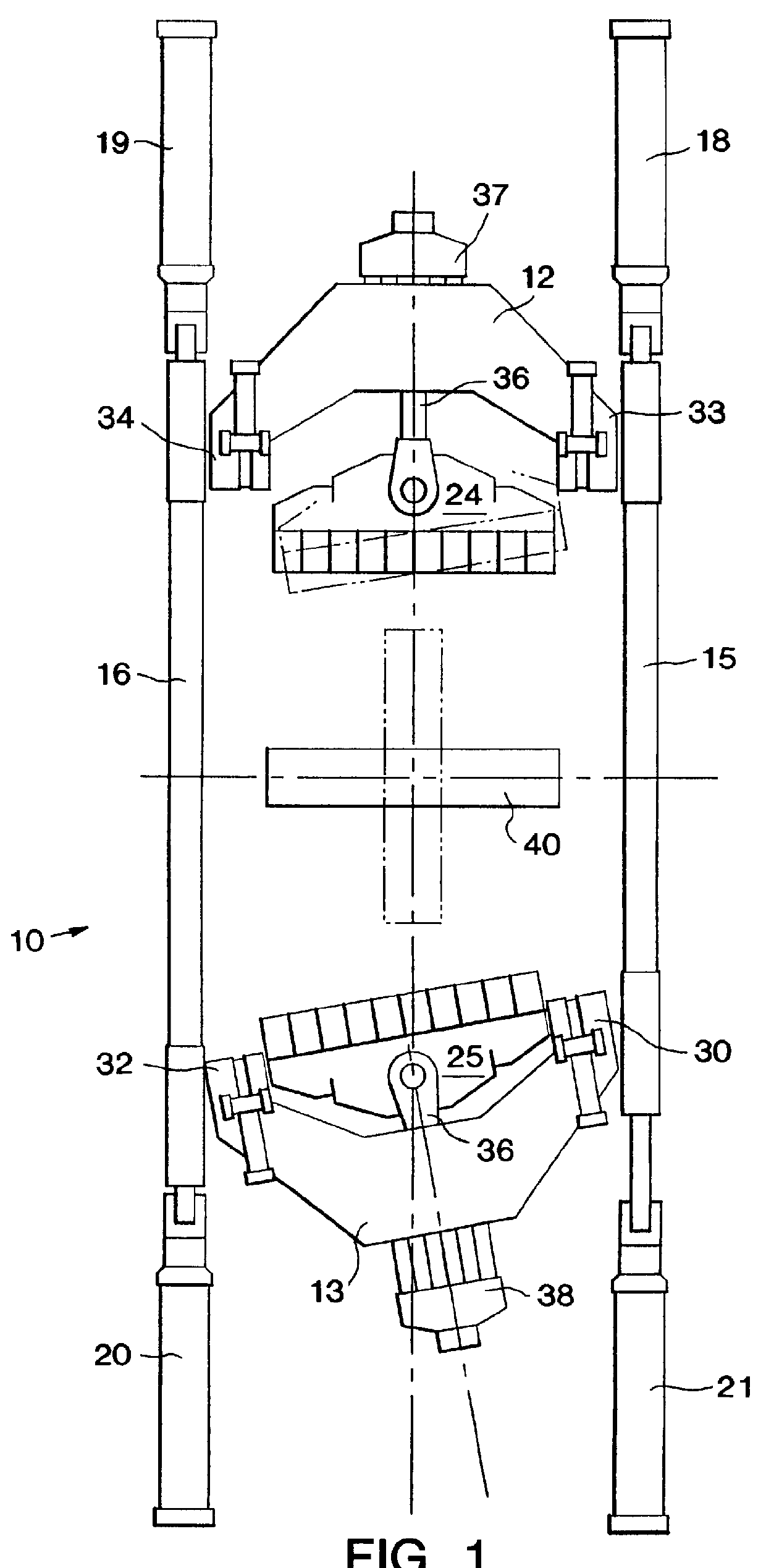
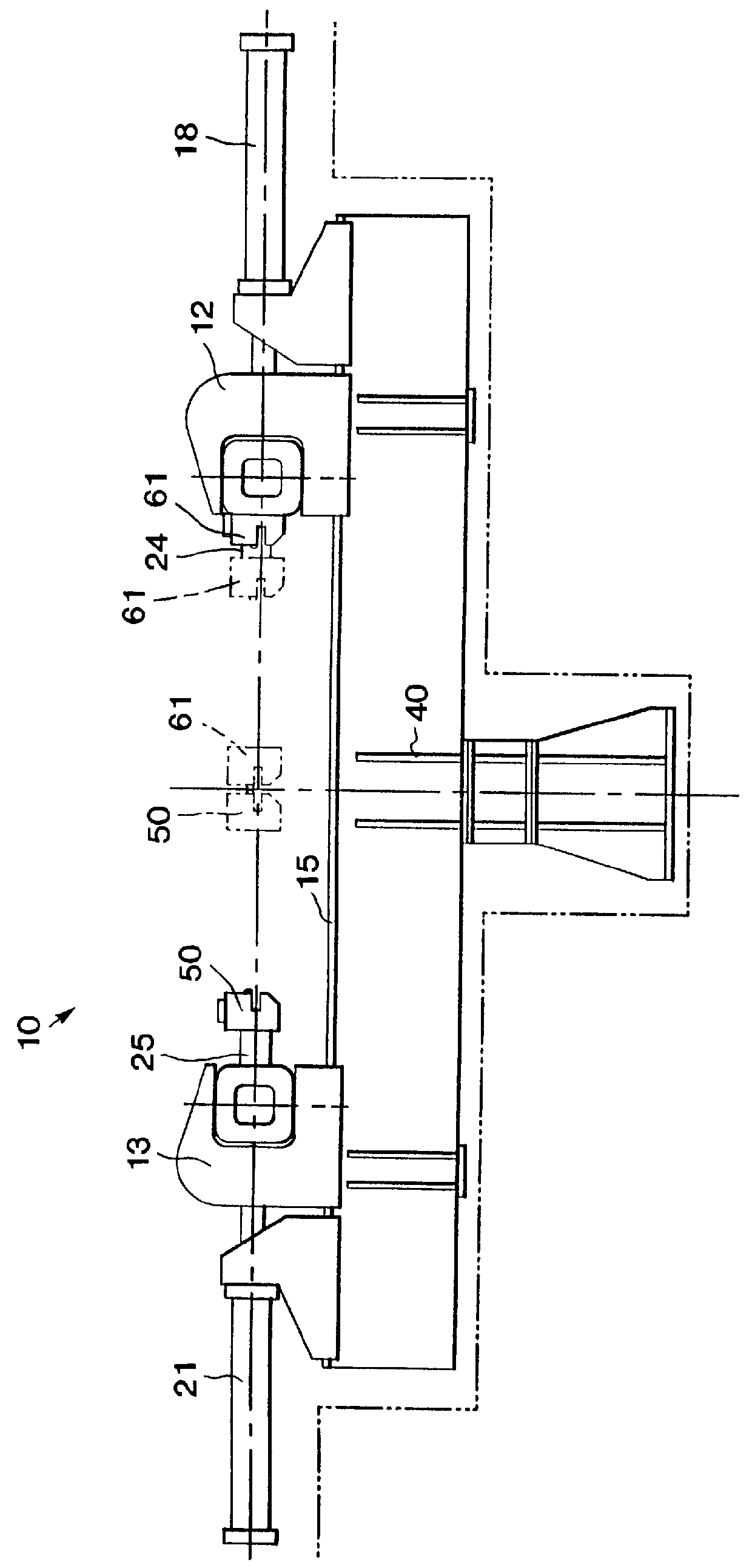
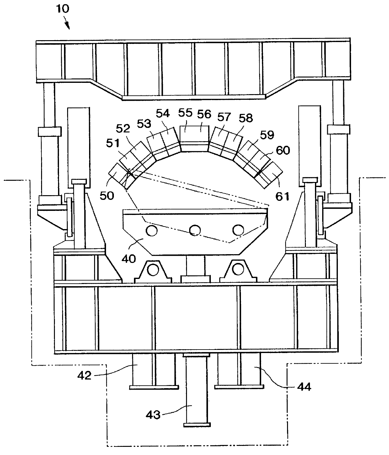
Referring now specifically to the drawings, a stretch-forming machine 10 according to an embodiment of the invention is shown in simplified form in FIGS. 1, 2 and 3. As generally shown, the stretch-forming machine 10 comprises a pair of yokes 12 and 13 riding on respective beam ways 15, 16 and actuated by carriage cylinders 18, 19 and 20, 21, respectively. Yokes 12 and 13 carry respective jaws 24, 25, each of which are mounted for movement on several axes.

Jaw angulation (FIG. 1) is provided by asymmetric movement of the carriage cylinders 18, 19 (jaw 24) and carriage cylinders 20, 21 (jaw 25).

Oscillation of jaws 24 and 25 is provided by oscillation cylinders 26, 27 (FIG. 4B as to jaw 24) carried on the jaws 24, 25 themselves. Jaw rotation is provided by rotation cylinders 30, 31 which interconnect the yokes 12, 13 and respective jaws 24, 25 and permit the jaws 24, 25 to be rotated rotate about a longitudinal horizontal axis relative to the yokes 12, 13 during sheet loading and formi...


PUM

PropertyMeasurementUnit
shapeaaaaaaaaaa
mechanical adjustmentaaaaaaaaaa
hydraulic pressuresaaaaaaaaaa

Abstract

A stretch-forming machine of the type wherein a pair of opposed curving jaws grips opposing ends of a metal sheet to be stretch-formed in a curved configuration. Each of the jaws are formed of an array of adjacent grippers movable relative to each other by respective hydraulic cylinders to define a part of the curve of the jaw. The improvement to the stretch-forming machine which is the subject of this application comprises a closed-loop servo-control means for moving each one of the grippers into a predetermined position relative to each other. Each of the servo-control means comprises a hydraulic cylinder position controller carried by the hydraulic cylinder of the one gripper for controlling hydraulic fluid flow to the hydraulic cylinder responsive to stored data representing the desired predetermined position of one of the grippers. A motor is provided for actuating the position controller in response to the data received by the position controller to move the hydraulic cylinder. Hydraulic cylinder position feedback means is positioned on the hydraulic cylinder for sensing the position of the hydraulic cylinder and communicating a signal representing the position of the hydraulic cylinder to the position controller.

Description

TECHNICAL FIELD AND BACKGROUND OF THE INVENTIONThis invention relates to a closed loop servo-controlled stretch-forming machine of the type having two opposed clamping jaws. While the term "stretch-forming" is used in this application, the invention is intended to have application to any type of metal-forming machine wherein jaws are comprised of a number of adjacent grippers which are collectively curvable so as to more closely conform to the shape to be imparted to the metal.The clamping jaws are formed of a series of hinged grippers move relative to each other in such a manner as to collectively form concave, convex or lazy-S curves. These opposed jaws are used to grip opposing ends of a metal sheet while the sheet is stretched into its yield state and while in that state is formed over a die. Each of the grippers is actuated against a mechanical or electrical stop by hydraulic cylinders so that the gripped sheet can be loaded flat, then caused to assume a contour roughly in the ...

Claims


Application Information

Patent Timeline
Patent Type & Authority Patents(United States)
IPC IPC(8): B21D11/02B21D11/00B21D25/00B21D25/04B21D43/10
CPCB21D11/02B21D25/00
Inventor FORD, JESSE CARLPOLEN, LARRY ALEXANDER
Owner CYRIL BATH
Why Eureka
Try Eureka