Driving circuit for high intensity discharge lamp electronic ballast

a technology of electronic ballast and driving circuit, which is applied in the direction of electric variable regulation, process and machine control, instruments, etc., can solve the problems of high circulating resonant current, hard switching mode, and inability to generate high ignition voltage using the resonant method, so as to avoid excessive current and voltage, the effect of improving performan

Inactive Publication Date: 2000-02-01
MATSUSHITA ELECTRIC WORKS LTD
View PDF4 Cites 108 Cited by
  • Summary
  • Abstract
  • Description
  • Claims
  • Application Information

AI Technical Summary

Benefits of technology

Optionally, the switching elements operate in zero current switching mode during normal operation, and / or in resonant mode during starting. Optionally, the current source inductor should be directly in series with the high intensity discharge lamp and the lamp should be in parallel with an ignition capacitor of no less than approximately 0.5 nano-farads, and further optionally approximately 0.5-10 nF, and still further optionally approximately 1-3 nF. This arrangement improves performance when the switching elements have soft switching or ZCS switching during switch turn-on, yet maintain continuous current in the current source inductor. Further optionally, the switching elements are in half bridge configuration or in full bridge configuration.
The control circuitry is connected to sweep the frequency of AC ignition voltage during starting through a range that includes the second resonant frequency formed by the second stage inductor and the second stage capacitor. This arrangement helps in avoiding excessive current and voltage imposed on the second stage resonant elements.

Problems solved by technology

Accordingly, generation of a high ignition voltage using the resonant method necessarily suffers from high circulating resonant current in the resonant elements and driving source switches.
The disadvantages of this arrangement become apparent when it is considered that the high frequency attenuation is only -20 dB / decade (logarithmic decade) for frequencies above the corner frequency (the corner frequency being formed by the lamp LMP impedance and the inductance L1b).
Another disadvantage of this arrangement is that the switching elements Q1b, Q2b are in hard switching mode during the switch turn-on interval.
The necessary switches are expensive because external ultra-fast freewheeling diodes in the order of 20-50 nS reverse recovery time are required.
Moreover, switching losses are relatively high.
A drawback of the circuit of Allison et al. is that the attenuation factor is highly sensitive to the frequency variation of the buck converter.
Fundamentally, the disclosure of Nagase et al. has the same disadvantages as the comparative example of FIG. 1 of the present disclosure in discontinuous mode operation, except that resonant ignition is implied.

Method used


Image

  • Driving circuit for high intensity discharge lamp electronic ballast
  • Driving circuit for high intensity discharge lamp electronic ballast
  • Driving circuit for high intensity discharge lamp electronic ballast

Examples


second embodiment

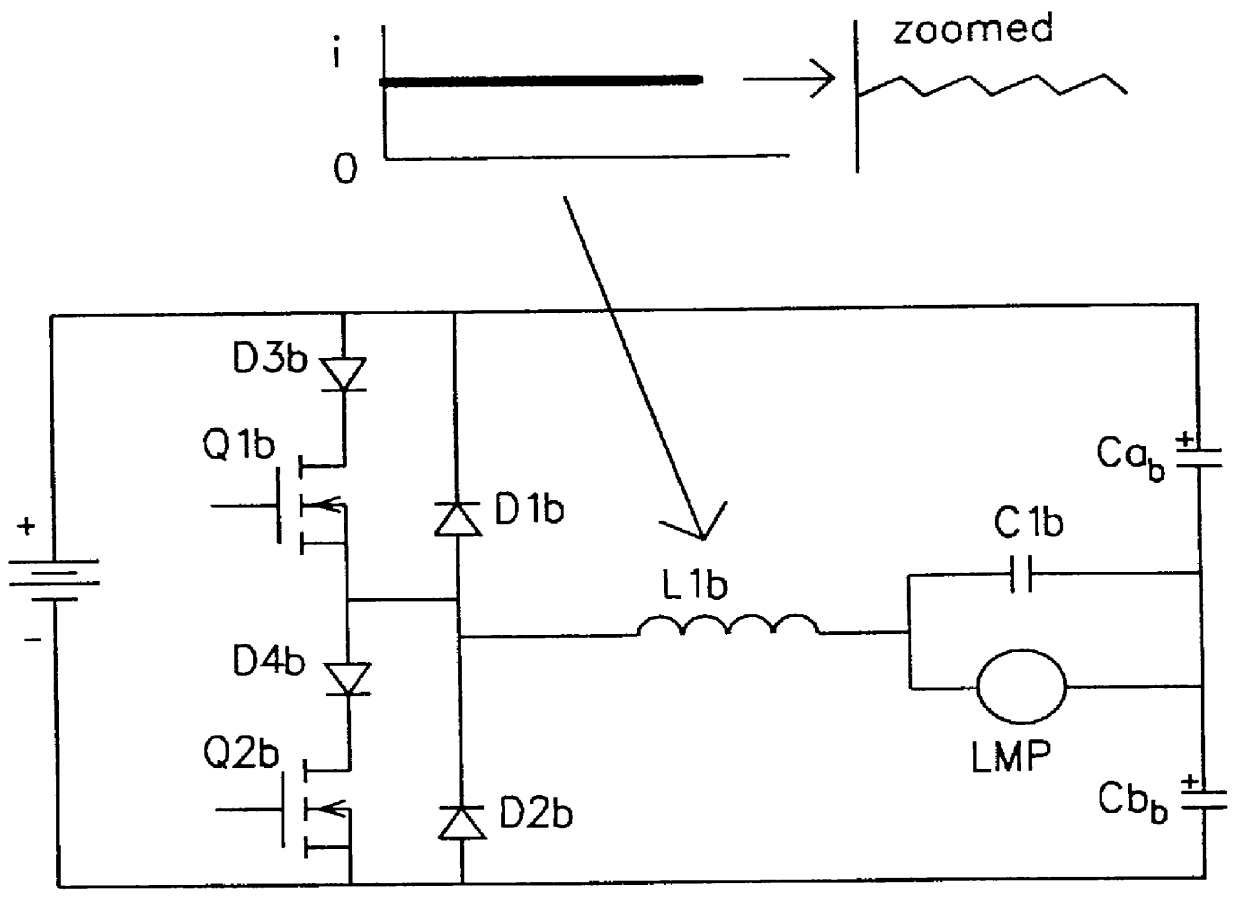
FIG. 14A shows the invention, substantially corresponding to the circuit of FIG. 3, but in full bridge configuration. In the alternative topological arrangements shown in FIG. 14A and 14B, the energy storage elements Ca and Cb can be replaced by a pair of active switches Q3 and Q4, forming a full bridge scheme in conjunction with the first switching element Q1 and the second switching element Q2. Accordingly, the switching elements Q1, Q2, Q3, and Q4 are in full bridge configuration. In FIGS. 14A and 14B, the control unit 1 is not shown, but all of the active switches Q1, Q2, 3, and Q4 are connected to the control unit 1 in the manner shown in FIG. 3 with respect to the switching elements Q1 and Q2, and are controlled thereby. In the full bridge configuration shown in FIG. 14A, the lamp current is sensed through the lamp LMP directly, or through the first stage inductance L1 indirectly.

It should be noted that FIGS. 14A and 14B show an arrangement in which the switching elements Q1 a...

first embodiment

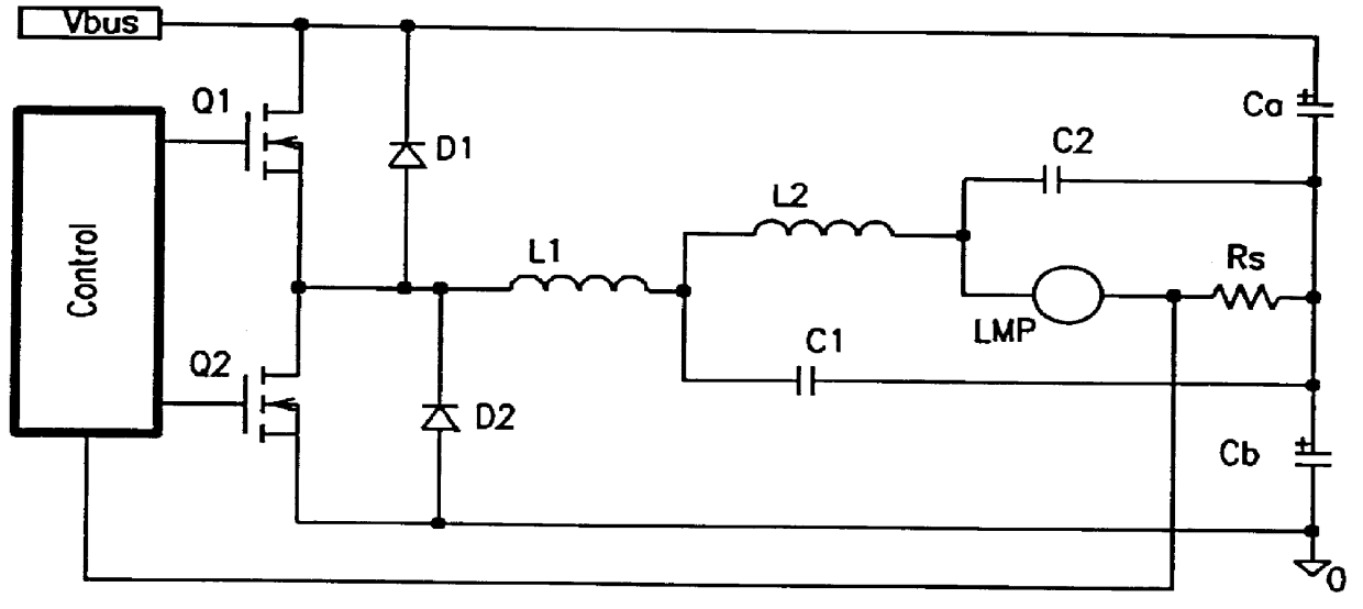
The operation of the full bridge portion of the circuit of FIG. 14A and 14B (e.g., excepting the two-stage filter including L1, C1, L2, C2 and attendant advantages) may be similar to or the same as disclosed in commonly assigned U.S. patent application Ser. No. 08 / 783,557, filed Jan. 14, 1997, inventor(s) Ajay Maheshwari et al., the disclosure of which is expressly incorporated by reference herein in its entirety. The operation of the two-stage filter of FIGS. 14A and 14B is essentially as disclosed above with respect to the description of the


PUM


Abstract

A circuit arrangement and control thereof for igniting a high intensity discharge (HID) lamp, for reducing the high frequency ripple superimposed on the low frequency rectangular waveform lamp current after ignition, and for increased circuit efficiency. The high frequency ignition voltage is only applied to the lamp during ignition phase and is mainly generated by the second stage of the low pass (LP) filter. The first stage of the LP filter whose resonant frequency is below the second stage further attenuates the high frequency ripple current through the lamp in normal operation. The resulting lamp current is a low frequency rectangular wave with less than 10% high frequency ripple. Acoustic resonance is avoided. The inductor in the first stage of LP filter is operated in discontinuous current mode. Doing so, the active switches are in zero current switching (ZCS) to maximize the circuit efficiency.

Description

1. Field of the InventionThe present invention relates to a circuit arrangement and control method for generating high frequency sinusoidal voltage for igniting a high intensity discharge (HID) lamp, and for maintaining stable lamp arc operation with minimal high frequency ripple superimposed on a low frequency rectangular lamp current.2. Description of Background InformationIn electronic high intensity discharge lamp ballasts, there are two distinctly different methods to drive the lamp. The first method is to drive the lamp with high frequency sinusoidal current, and the second is to drive the lamp with low frequency rectangular current. The high frequency sinusoidal current method tends to give rise to acoustic resonance. Accordingly, low frequency rectangular current wave operation remains the favored technique for electronic high intensity discharge lamp ballasts because of the acoustic resonance problem associated with the high frequency method.Two fundamental approaches are g...

Claims


Application Information

Patent Timeline
Patent Type & Authority Patents(United States)
IPC IPC(8): H05B41/38H05B41/288H05B41/28
CPCH05B41/2883H05B41/2887H05B41/2888H05B41/388Y02B20/204Y10S315/07Y10S315/05Y02B20/00
Inventor SUN, YIYOUNGGORIKI, TAKESHI
Owner MATSUSHITA ELECTRIC WORKS LTD
Why Eureka
Try Eureka