Piggyback magneto-resistive read/write tape head with optimized process for same gap read/write

Inactive Publication Date: 2000-03-14
IBM CORP
View PDF18 Cites 47 Cited by
  • Summary
  • Abstract
  • Description
  • Claims
  • Application Information

AI Technical Summary

Benefits of technology

(2) The piggyback design greatly reduces the spacing of the write element and the corresponding read verify element. The advantage is that the verify time is therefore reduced and this reduces buffer size, error detection time, and correction time.
(3) The conductive underlayer under the HFB (CoPtCr) butting the magneto-resistive layer reduces the read element resistance which therefore will result in both a lower bias voltage drop and I.sup.2 R heating of the head. This reduces the potential for tape stick and tape damage. This also allows the head designer greater flexibility in laying out the read element leads as the length of the leads would be less of an impact on read circuit resistance.
(4) The wear shield layer has a significant mechanical hardness improvement over alternate insulation layer materials which results in less gap erosion. This would greatly increase the expected life of the head.
(5) The grounding of the

Problems solved by technology

In a two-gap magnetic recording head, a single read head and a single write head are provided side-by-side, resulting in possible misalignments on the order of only a few micrometers.
However, current tape head designs do not provide for same gap read/write function requiring the read-while-write sensor to be positioned on an opposing module.
The cost of mechanically aligning the opposing modules to the required tolerances has become a major cost concern, and in the case of unidirectional application forces the fabrication of the opposing module at a double film cost.
Existing designs do not address common high coercivity media (900 to 1,800 Oe) concerns s

Method used


Image

  • Piggyback magneto-resistive read/write tape head with optimized process for same gap read/write
  • Piggyback magneto-resistive read/write tape head with optimized process for same gap read/write
  • Piggyback magneto-resistive read/write tape head with optimized process for same gap read/write

Examples


Embodiment Construction

A. Construction of Read / Write Head

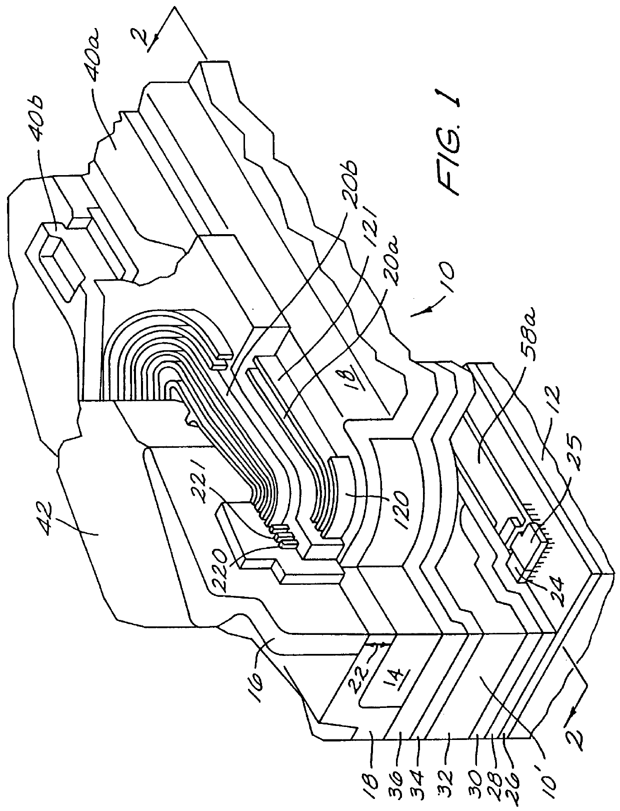
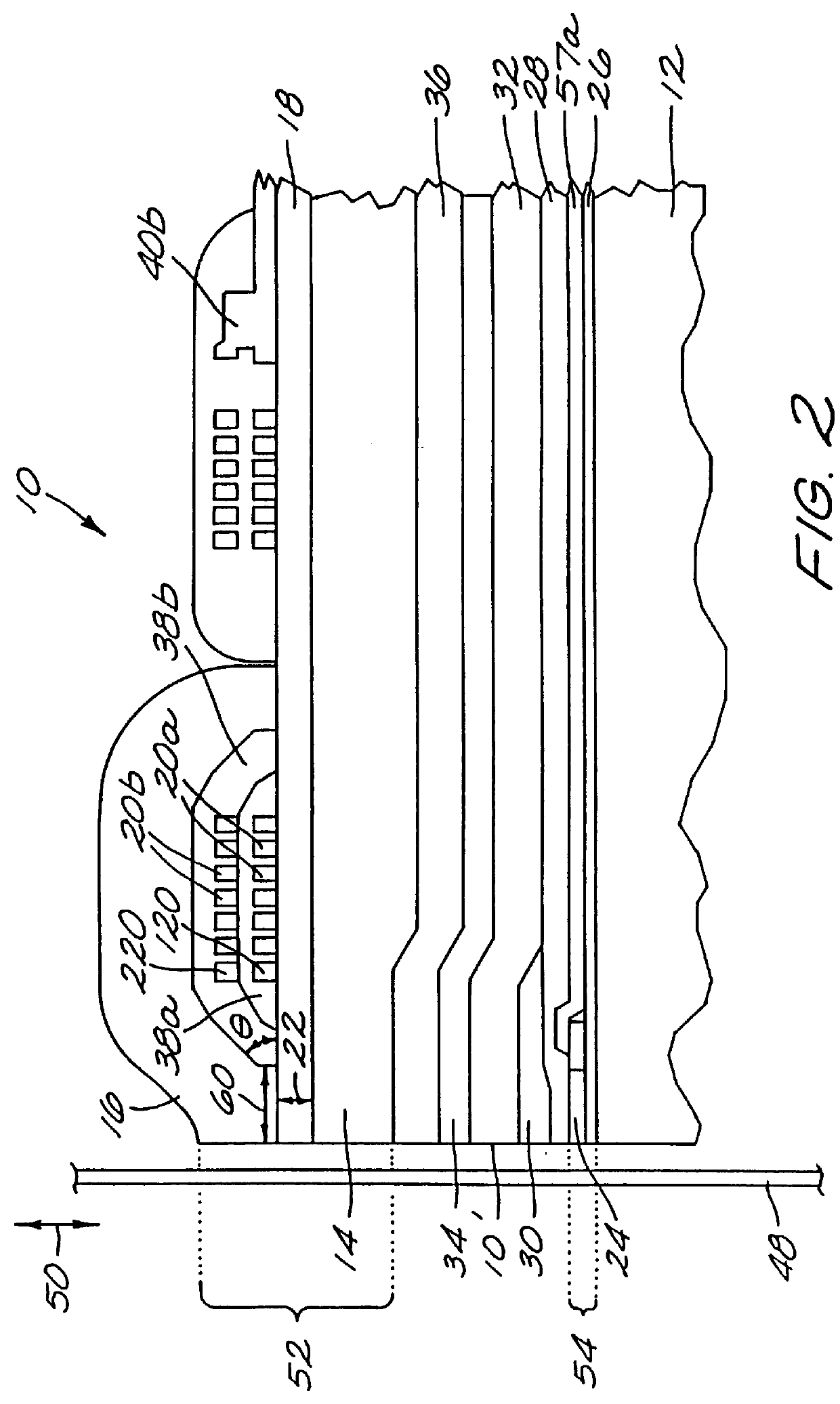
Referring now to the drawings, wherein like reference numerals depict like elements throughout, FIG. 1 shows a cross-section of the piggy-back write read construction of the thin film magnetic head 10 of the present invention and the various shields employed for use in contact recording on flexible magnetic media, such as magnetic tape (not shown in FIG. 1, but visible in FIG. 2). The magnetic head 10 includes a magnetic substrate 12, generally made of a magnetic ceramic, such as nickel zinc ferrite. A non-magnetic substrate can also be used. This could be an Al.sub.2 O.sub.3 --TiC substrate covered by a magnetic shield similar to the shield described below (layer 30), having a thickness of about 1 to 2 .mu.m, and an insulator material. This composite is equivalent to the magnetic substrate 12. A first thin film pole write piece 14, denoted P1, generally made of a Permalloy (e.g., nickel-iron), or multilayer Permalloy / iron laminate and / or amorphous ...


PUM


Abstract

A magneto-resistive read/write tape head is provided for reading and writing to tape media along a tape head face. The tape head comprises a plurality of modules, each module comprising a read element and a write element spaced apart and terminating at the tape head face and formed over a substrate. The read element comprises a soft film bias layer and a hard film bias layer butted against the SFB layer. The write element comprises two pole tips spaced apart by a gap. The tape head further includes a plurality of activating conducting coil turns operatively associated with the write element and covered by a cross-linked photoresist and positioned between the gap and one of the pole tips and set back from the tape head face. The tape head has at least one of the following elements: (a) a wear shield between the read element and the write element for limiting wear of the gap between the two pole tips, the wear shield being grounded for decoupling read and write functions of the tape head, for allowing same module read/servo/write functions simultaneously, and for grounding static charge from the tape media; (b) a layer of electrically conductive and corrosion-resis tant material, such as rhodium, under the hard film bias layer to reduce its resistance; and (c) a non-activating dummy coil turn closer to the pole tips than the activating coil turns for defining a forward termination of the cross-linked photoresist between the activating coil turns and the tape head face to thereby provide improved ease of processability.

Description

The present invention relates generally to magnetic recording, and, more particularly, to a thin film magneto-resistive (MR) head having same module read / write / servo functions.Business, science, and entertainment applications depend upon computers to process and record data, often with large volumes of data being stored or transferred to non-volatile storage media. The non-volatile storage media typically include magnetic discs, magnetic tape cartridges, optical disk cartridges, floppy diskettes, or floptical diskettes. The advantages of storing data on non-volatile storage media are numerous, including: a capability of storing hundreds of megabytes or even gigabytes of data (additional cartridges can be used to store still more data); providing a vehicle for long term storage and archival; backing up that data which resides on non-removable media; and providing a convenient vehicle for transferring data between computers. Typically, magnetic tape media is the most economical means ...

Claims


Application Information

Patent Timeline
IPC IPC(8): G11B5/40G11B5/31G11B5/39G11B5/17G11B5/10G11B5/11
CPCG11B5/3146G11B5/3903G11B5/3967G11B5/40G11B5/11G11B5/17G11B5/3133G11B5/3163
Inventor ABOAF, JOSEPH ADAMDENISON, EDWARD VIRGILFRIEDMAN, JULES DAVIDKAHWATY, VINCENT NOELKLUGE, II, HERMAN CARL
Owner IBM CORP
Why Eureka
Try Eureka