Optical interconnect

a technology of optical interconnection and optical fiber, applied in the field of optical interconnection system, can solve the problems of limiting the performance of the system, limiting the density of the channel pack across the width of the card, and inefficient use of the available area

a technology of optical interconnection and optical fiber, applied in the field of optical interconnection system, can solve the problems of limiting the performance of the system, limiting the density of the channel pack across the width of the card, and inefficient use of the available area

US6055099AInactive Publication Date: 2000-04-25BRITISH TELECOMM PLC

Image

  • Optical interconnect
  • Optical interconnect
  • Optical interconnect

Examples


Embodiment Construction

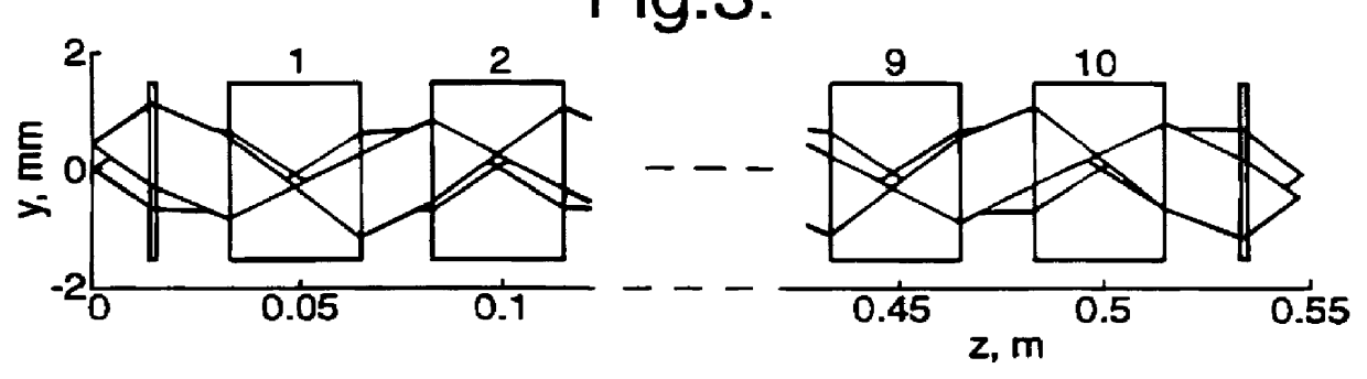
An optical interconnect system includes a substrate 1 (FIG. 5) and an optical image relay system 2 mounted on the substrate 1. The relay system comprises a number of glass rods 3. Each glass rod 3 has spherical end surfaces 4, 5. In the present example ten rods 3 are used, although for clarity four only of the rods are shown in FIG. 5. The rods act as a 4f system, so termed because the repeat unit of the optical system has a length equal to four times the focal length of the lenses, as in illustrated in FIG. 2. The discrete lens elements shown in FIG. 2 are replaced in the present embodiment by the spherical end surfaces of the rod 3.

FIG. 9 shows the profile of one of the glass rods 3. In this example, the rod is formed from SF11 glass manufactured by Schott and having a uniform refractive index of 1.767 at 760 nm. The length of the rod is 30.83.+-.0.08 mm, the diameter is 5.00.+-.0.08 mm and the centration errors are .ltoreq.0.08 mm. The end surfaces 4, 5 have spherical surface rad...


PUM


Abstract

PCT No. PCT / GB97 / 00430 Sec. 371 Date Apr. 13, 1998 Sec. 102(e) Date Apr. 13, 1998 PCT Filed Feb. 14, 1997 PCT Pub. No. WO97 / 31280 PCT Pub. Date Aug. 28, 1997An optical interconnect is formed form a series of coaxially aligned lenses. The lenses are spaced apart along a planar substrate and form repeated images of an optical array at the input to the interconnect. Outputs ports are located at different points along the interconnect. Each of the pair of lenses enclosing one of the repeated images is formed as a single physically integral member. This member may take the form of a transparent rod having spherical end surfaces. Each of the spherical end surfaces then provides one of the pair of lenses.

Description

1. Field of the InventionThe present invention relates to an optical interconnect system, and in particular to a backplane interconnect. Such an optical backplane might be used, for example, as a broadband interconnect for a multiprocessor computer system or in a switch for a broadband optical telecommunications system.2. Related ArtA backplane interconnect system is typically required to provide many parallel data channels running across its width with access points at different locations along its length. Cards carrying interface and signal processing circuits may be fitted to the backplane at the different access points. When such an interconnect is used in a complex system, such as a switch in a telecommunications system, then it may have to accommodate a large number of cards. In these circumstances, if a conventional electrical backplane is used, then the limited bandwidth of the interconnect and crosstalk between different channels on the interconnect become significant facto...

Claims


Application Information

Patent Timeline
25 Apr 2000
Publication
US6055099A
IPC
G02B6/43; G02B6/42
CPC
G02B6/43
Inventors
WEBB, RODERICK P