Heat maps for controlling deformations in optical components

a technology of heat maps and optical components, applied in the direction of heat measurement, optical radiation measurement, instruments, etc., can solve the problems of reducing the performance of the laser system, limiting the beneficial size reduction of the high-power laser system, and unheating of the optical components of the laser system

Inactive Publication Date: 2000-05-23
RAYTHEON CO
View PDF10 Cites 33 Cited by
  • Summary
  • Abstract
  • Description
  • Claims
  • Application Information

AI Technical Summary

Problems solved by technology

High energy laser beams often have uneven beam intensity profiles that result in uneven heating of laser system optical components.
The uneven heating tends to distort optical components, changing the refractive and reflective properties of the components, decreasing laser system performance.
Resulting component distortions often limit beneficial size reductions of high power laser systems and place costly design constraints on the systems.
Temperature related distortions are particularly problematic in the aperture sharing element of a laser system.
Uncompensated aperture sharing element distortions reduce the aiming and focusing capability of the laser system.
These materials are expensive and typically do not eliminate component deformations.
Additional complicated circuitry and optical components such as deformable mirrors make these systems expensive and bulky.
Large physical spacings required for the actuators result in bulky deformable mirrors.
Also, driving the actuators requires high voltages and expensive amplifiers.
In addition, the mirrors cannot quickly control very small mirror movements.
This limits the overall effectiveness of the deformable mirrors.

Method used


Image

  • Heat maps for controlling deformations in optical components
  • Heat maps for controlling deformations in optical components
  • Heat maps for controlling deformations in optical components

Examples


embodiment 70

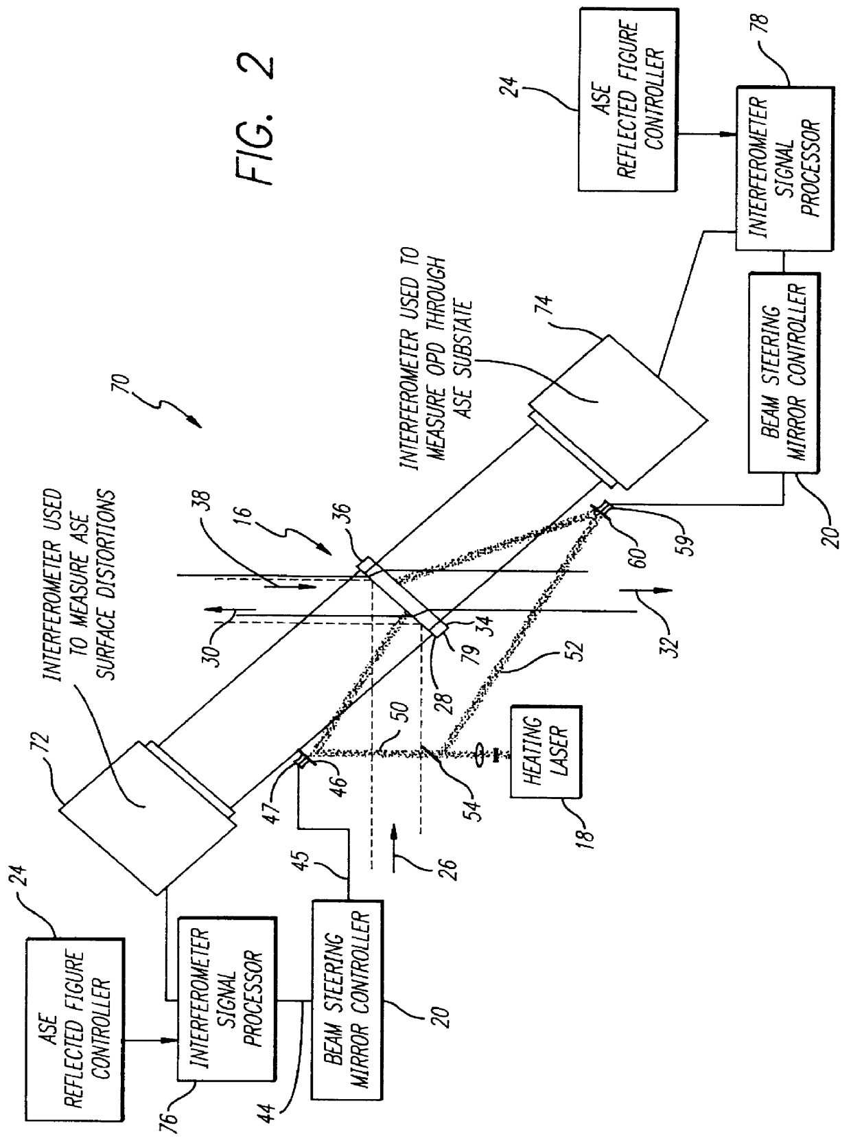
FIG. 2 is a diagram of a first alternative embodiment 70 of the deformation control system of the present invention utilizing interferometers 72, 74. The operation of the system 70 is similar to the operation of the system 10 of FIG. 1 with the exception that the infrared cameras and camera controllers are replaced by interferometers 72, 74 and interferometer signal processors 76, 78.

The first interferometer 72 measures the distortion pattern on the first ASE surface 28 rather than the temperature pattern. The distortion pattern is used by the first interferometer signal processor 76 running the control algorithm supplied by the figure controller 24 to provide the heat pattern signals 44 to the beam steering mirror controller 20. The mirror controller 20 supplies actuator control signals 45 to the actuator 47 to selectively actuate the mirror 46 to heat the surface 28 in a pattern complimentary to the distortion pattern measured by the interferometer 72.

The second interferometer 74 ...

embodiment 90

FIG. 4 is a diagram of a third alternative embodiment 90 of the present invention having a heat map forming surface 92 and an open-loop controller 94. Information from a laser beam generation system 96 corresponding to the beam 26 irradiance pattern is supplied to the open loop controller 94 via a controller bus 98. The beam generation system 96 has an irradiance sensor (not shown) that provides this information. The open loop controller 94 utilizes the information supplied via the bus 98 to determine an appropriate heat pattern to be applied to the surface 28 to make the surface temperature uniform. The heat pattern is converted into electronic control signals 100 that control the movement of the actuator 102. The actuator 102 in turn controls the movement of a beam steering mirror 104 connected to the actuator 102.

The heating laser 18 provides the heating beam 48 which is directed to the mirror 104. The heating beam 48 reflects off the selectively actuated mirror 104 onto the heat...

embodiment 110

FIG. 5 is a diagram of a fourth alternative embodiment 110 of the present invention having a predetermined heat mask 112. Previous information about the irradiance profile of the high-energy laser beam 26 obtained from the laser beam generation system 96 is used to form the heat mask 112.

The exemplary heat mask 112 is an opaque coating 114 that is applied to a transparent mask substrate 116. The coating 114 may be a metallic optical grade coating having varying degrees of thickness, and corresponding varying degrees of reflectivity. The reflectivity varies in accordance with the irradiance profile of the beam 26. This coating 114 may be deposited on the mask substrate 116 using conventional depostion methods. The coating 114 may be an electrically actuated liquid crystal heat mask without departing from the scope of the present invention.

An infrared energy radiator radiates infrared energy 120 onto the heat mask 112. Infrared energy 122 is transmitted through the heat mask 112 in pa...


PUM


Abstract

A system (80) for controlling deformations of optical components adapted for use with laser system aperture sharing elements (16) and deformable mirrors. The inventive system (80) includes a control loop (12, 40, 24, 20, 46, 28, 74, 78, 60, 34) for determining a desired temperature pattern. The control loop (12, 40, 24, 46, 28, 74, 78, 60, 34) provides a control signal (45) corresponding to the desired temperature pattern to a heat map applicator (18, 46, 47, 59, 60). The heat map applicator (18, 46, 47, 59, 60) applies the desired temperature pattern to the optical component (16) in response to the control signal and the optical component (16) is selectively deformed in response thereto. In a specific embodiment, the control loop (12, 40, 24, 20, 46, 28, 74, 78, 60, 34) is a closed loop control system that includes an interferometer (74). The interferometer (74) provides a first shape of the optical component (16) to a comparator circuit (20) that compares the first shape to a desired shape corresponding to the desired temperature pattern for determining the control signal. An alternative closed loop control system (12, 40, 24, 20, 46, 28, 74, 78, 60, 34) includes an infrared energy detector (12) that determines a current temperature pattern and generates the control signal in response thereto for converting the current temperature pattern to the desired temperature pattern. The heat map applicator (18, 46, 47, 59, 60) provides an electromagnetic beam (50, 52) that is swept across the optical component (16) to impart the desired temperature pattern on the optical component (16). In another illustrative embodiment, the control loop is an open loop control system that includes a complimentary electromagnetic energy beam that is swept over the optical component to form a heat pattern complimentary to the temperature pattern imparted to the optical component by a high power laser beam such that the total heat deposited on the optical component is uniform.

Description

1. Field of InventionThis invention relates to systems for controlling deformations in optical components. Specifically, the present invention relates to systems for controlling temperature related distortions of optical components in high power laser systems.2. Description of the Related ArtHigh power laser systems are used in a variety of demanding applications ranging from target aiming systems to precision cutting devices. Such applications require systems with very precise optical components and accurate aiming capability.High power laser systems typically include several optical components such as deformable mirrors and beam splitters. High energy laser beams often have uneven beam intensity profiles that result in uneven heating of laser system optical components. The uneven heating tends to distort optical components, changing the refractive and reflective properties of the components, decreasing laser system performance.Typically, as the diameter of a laser beam decreases, ...

Claims


Application Information

Patent Timeline
Patent Type & Authority Patents(United States)
IPC IPC(8): G01B11/16
CPCG01B11/16
Inventor FINK, DAVID
Owner RAYTHEON CO
Why Eureka
Try Eureka