Laser etching of electroluminescent lamp electrode structures, and electroluminescent lamps produced thereby

a technology of electroluminescent lamps and electrode structures, applied in the direction of discharge tubes/lamp details, discharge tubes luminescnet screens, manufacturing tools, etc., can solve the problems of weakening the lamp, difficult to control the edges of the brush with precision, and high cost of laser beams directing laser beams through multiple overlying layers

Inactive Publication Date: 2000-05-23
ASTRONICS
View PDF41 Cites 71 Cited by
  • Summary
  • Abstract
  • Description
  • Claims
  • Application Information

AI Technical Summary

Problems solved by technology

Additionally, the technique of directing a laser beam through multiple overlying layers to ablate the top surface of the underlying layer is expensive and requires exacting precision.
This method, however, may undesirably result in removing material at different depths, since it is difficult to control the edges of the brush with precision.
This in turn can cause damage to the underlying substrate, thereby weakening the lamp.
Further, the narrow groove formed by the wire brushing could permit an electric arc to traverse the groove, thereby causing a short circuit.
The method, however, does not lend itself to complex lamp configurations and end product final lamp shapes.
The drawbacks to this approach include the difficulty of accurately controlling an electrode with a small needle tip that concentrates the electric charge, as well as removing the resulting scattered etched particles from the electrode substrate.
Furthermore, the use of significant voltages may create safety hazards.
In addition, the removal of an area of the conductive material, which is 10 microns in width, of itself, may not prevent electrical arcing, and consequently such processing may still result in significant risk of short-circuiting in the use and operation of the lamp constructed from such electrode.
As is the case with most of the prior art discussed, this method of electrode removal is applied during the manufacturing process of the EL lamp and is not practical for use with a completely layered EL laminate.
Accordingly, the portion of the lamp article having the front electrode cut away introduces a significant variation in thickness to the lamp, which may be detrimental from a packaging or aesthetic standpoint.
Further, the cutting operation introduces a processing step which increases the complexity of the manufacturing process, and which may result in damage to the metal coating incident to the severing of the portion to be excised, in connection with the stresses thereby imparted to the electrode layer at distances beyond the cut-out portion.
Such stresses may result in delamination of the metal film on the substrate, with consequent adverse effect on the performance of the resultant lamp article.
The only prior art method approach used to remove a portion of the conductive material on post-laminated EL lamp material is highly specific and not designed to remove relatively large regions of electrode material.
Further, the prior art emphasis on removal of conductive material from an electrode structure typically has focused on the front electrode and associated "lit" surface of the EL lamp, and the art has not addressed satisfactorily metal removal from the rear electrode for electrical isolation of the phosphor material.
Finally, none of the prior art approaches incorporate a technique for selectively forming the final EL lamp shape from a stock EL laminate material, or EL "blank" sheet.

Method used


Image

  • Laser etching of electroluminescent lamp electrode structures, and electroluminescent lamps produced thereby
  • Laser etching of electroluminescent lamp electrode structures, and electroluminescent lamps produced thereby
  • Laser etching of electroluminescent lamp electrode structures, and electroluminescent lamps produced thereby

Examples


Embodiment Construction

The disclosure of co-pending U.S. patent application Ser. No. 08 / 555,595 filed Nov. 9, 1995 now U.S. Pat. No. 5,757,125, in the names of Kim Furlong, et al. for "EL LAMP WITH LEAD ATTACHMENT ISOLATION STRUCTURE, AND ROTARY ABRASION METHOD OF MANUFACTURE THEREOF," now allowed, is hereby incorporated herein by reference, in its entirety.

The present invention overcomes the drawbacks of the prior art, as described in the "Background" section hereinabove, in the provision of improved EL lamps and an improved method for making such lamps.

The method of the invention achieves a considerable simplification of manufacturing over the prior art techniques of fabricating quick turn-around, off the shelf EL lamps.

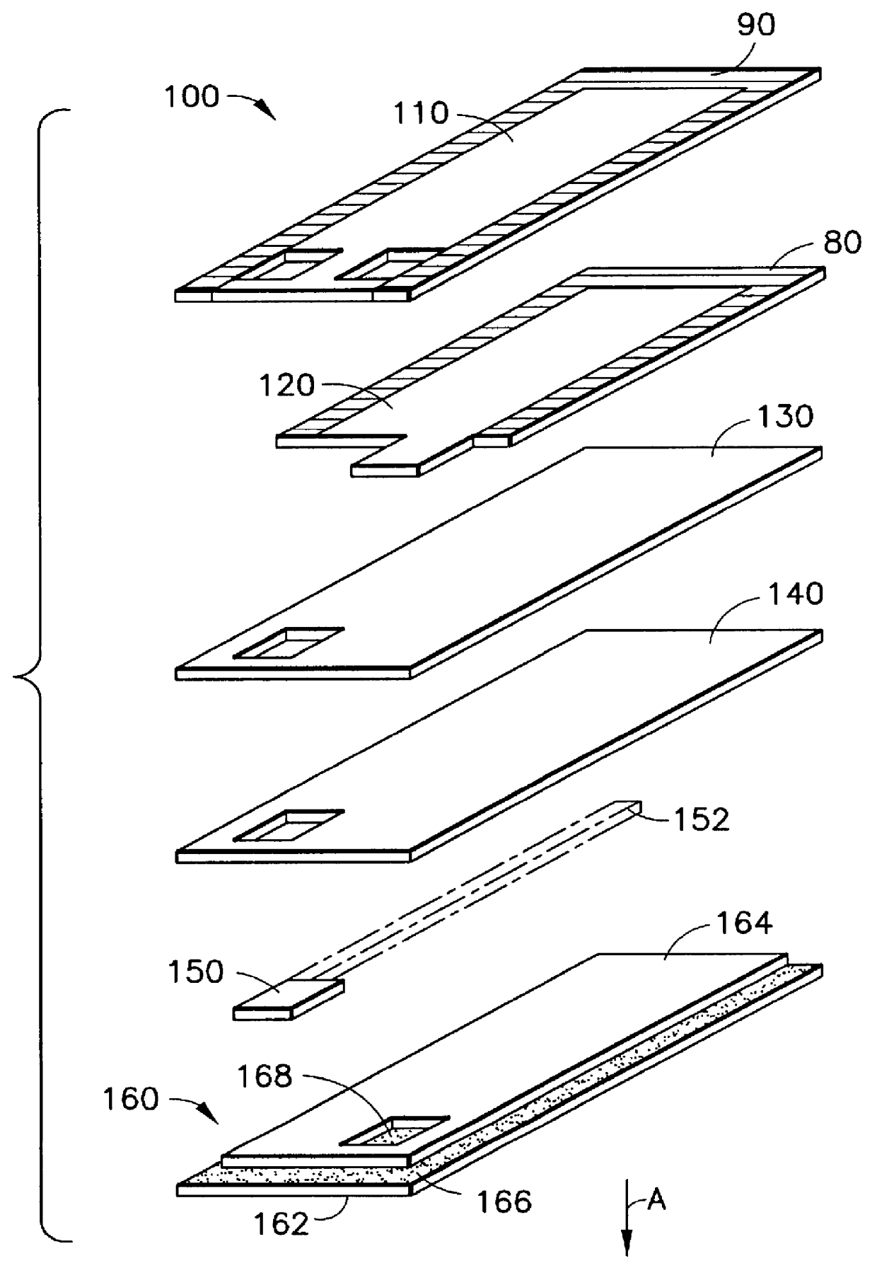
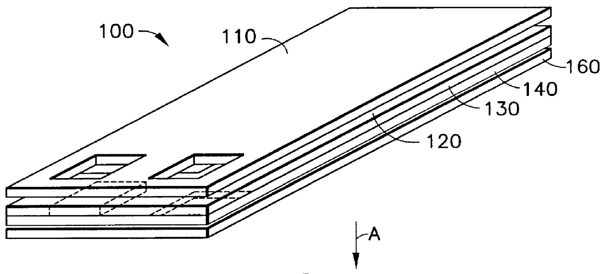
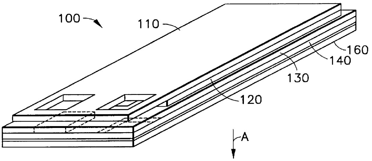
The EL lamp of the invention comprises a front electrode layer, a rear electrode layer, and disposed between these electrode layers, phosphor material and a dielectric layer. The terms "front" and "rear" in relation to the electrodes and electrode layer structures of the invention, are e...


PUM

PropertyMeasurementUnit
sizeaaaaaaaaaa
sizeaaaaaaaaaa
widthaaaaaaaaaa

Abstract

A process for manufacturing electroluminescent lamps using a laser beam to remove a material layer of a multi-layer material structure, in which the laser beam has a first energy level directed at a first material layer, e.g., a conductor, laid over a second material layer, e.g., an insulator / substrate. The laser beam is moved in an overlapping fashion such as spiral pattern motion across the first material layer. A part of the first material layer is sublimed exposing a region of the second material under the area where the spiral pattern was applied. Additionally, a second laser beam having a second energy level, e.g., higher than the first energy level, is moved along a path over the exposed second material layer subliming the remaining underlying layers to form the final lamp shape.

Description

1. Field of the InventionThe present invention relates to an improved method of manufacture of EL lamps, and to electroluminescent lamps produced thereby.2. Description of the Related ArtElectroluminescent ("EL") lamps commonly comprise a laminated assembly including phosphor material, a dielectric layer, and front and rear electrodes, with leads for applying an alternating electric field across the electrodes, to cause the phosphor to emit radiant (luminescent) energy, e.g., in the visible light spectrum, infrared, or ultraviolet spectrum.In such EL lamps, the phosphor material and dielectric layer between the electrodes, generally maintain the two electrodes in separated relationship to one another, thereby preventing them from short-circuiting.For such purpose, and to electrically isolate the phosphor layer from the rear electrode, it has been conventional practice to pattern the rear electrode conductive material, since the front electrode typically is formed as a continuous met...

Claims


Application Information

Patent Timeline
Patent Type & Authority Patents(United States)
IPC IPC(8): B23K26/073B23K26/00B23K26/06B23K26/08B23K26/40H05B33/10H05B33/12
CPCB23K26/073B23K26/08B23K26/0807H05B33/12B23K26/4005B23K26/4085H05B33/10B23K26/365B23K26/082B23K26/40B23K26/361B23K2103/16B23K2103/50
Inventor CLINE, DOUGLASSUPPLES, THOMASROSENBERGER, GEORGE
Owner ASTRONICS
Why Eureka
Try Eureka